Fuel Hanger Parts List:
- 1x Hat Body
- 1x 3/8 Barb fitting
- 2x 1/8NPT to 3/8 Barb fittings
- 1x 1/8NPT Plug fitting
- Outlet and Return Fittings (as ordered)
- 1x Long Round Bar Bracket
- 1x 2-pump bracket
- 1x 3Pin Pump Connector with wiring
- 1x 3Pin Sending Unit Connector with wiring
- 1x Hat to Chassis Ground
- 1x 3-wire Ground assembly
- 3x pink butt connectors
- 2x 3/8 Teflon Hoses, 30 inches long
- 1x 5/16 Teflon Hose, 30 inches long
- 4x pinch clamps
- 1x Top Tab
- 2x 10/32 x 3/8" long socket head screw's
- 1x 5/16 Jet Pump assembly
Optional Add-ons:
- 2x Fuel Pump
- 2x Fuel Pump install kit
- 2x Sock Filters
Note: This install was on a 96 Nissan 240sx, your fuel system may differ slightly but the install procedure will be the same.
Prior to installation, the entire factory fuel hanger should be removed from the tank, including the fuel sending unit
Step 1
Remove the factory carpet behind the rear seat to gain access to the fuel tank cover

There are 2 small Christmas tree clips that must be removed

Step 2
Now that you have gained access to the fuel cover, remove the 4 bolts to expose the fuel pump hanger.

Remove the factory fuel pump hanger, and fuel pump bracket including the top tab inside the fuel tank.


Step 3
Slide the pumps up through the pump bracket. Before tightening the bracket around the pump, push the hose onto the barb fittings in the fuel hat. REMEMBER TO FIRST HAVE YOUR HOSE CLAMPS ON THE HOSE FIRST! It is not easy to remove the hose from the barbs once installed.
After installing the fuel pumps to the bracket, tighten the pump bracket around the pump at the desired position.


Step 4
Attach the Teflon hose to the fuel pumps. It is easer to install these onto the pumps first rather than the hanger. Slip over the pinch clamps on to each hose.

Step 5
Using special crimping tool or a pair of dykes, crimp the pinch clamp snuggly around the hose. Be careful not to overtighten the clamps or they can be damaged. As an alternative you can use worm-gear clamps instead.
Step 6
Now your fuel pump bracket should look like this.
Note: The position of the rod can go either way but for ease of install it MUST look like this

Step 7
Remove the factory fuel sending unit and bracket prior to attempting to install the fuel pump bracket

Step 8
Install the fuel pump bracket into the tank. Make sure the pumps are going to the left pocket portion of the tank as seen below. It will NOT work if you go into the right hand pocket when you reinstall the fuel level sending unit.

NOTE: Some tanks have 2 ears that make installation a little difficult. For easier install get the pumps where you like, and then position the rod to the right and push it into the pocket.
Step 9
Install the top Bracket of the fuel pump bracket assembly
Step 10
Attach the rod to the top tab of the fuel tank you previously installed. Attach the m6 locknut and tighten.
Note: You may need to install the fuel level sending unit bracket itself to the tank before tightening the rod to the top bracket/tab

Now that you have installed the fuel pumps to the top bracket you can reinstall the factory fuel sending unit. Make sure you connect this unit back to the appropriate factory connector inside the tank
Step 11
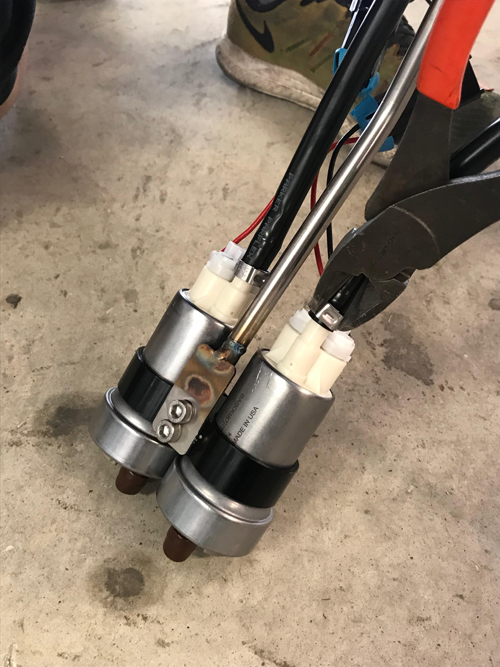
Connect the fuel pumps to the PHR fuel pump wires.
If using connectors for the fuel pumps, crimp the terminals to the end of the fuel pump wires (each pump should get a red power wire from the pump connector and a black ground wire from the ground harness. Make sure to position them in the correct location on the connector so they are not reversed.
As an alternative, you can connect the pumps using butt connectors if you did not purchase a fuel pump install kit.
Secure the connectors out of the way of the fuel level sending unit so they do not interfere with where the sending unit will sit. See the picture below.

Step 12
Now you are ready to install the fuel hat. You must re-use the factory sealing grommet for the fuel pump hanger assembly

Step 13
Wire the sending unit to the fuel hat sending unit connector wires. These are the smaller gauge red, black and white wires.
The wires should be connected as follows:
Black from sending unit to black on hanger
Green from sending unit to red on hanger
White from sending unit to white on hanger
SENDING UNIT WIRES MAY CHANGE DEPENDING ON YEAR AND VEHICLE, SOME LATE MODELS INCLUDED FUEL TEMP SENSORS THAT WILL NOT BE REQUIRED
Be sure to zip tie or secure the wires so they will not interfere with the sending unit.
These are the wires located on the inside of the tank

Step 14
In order for the tie down nut to fit around the bosses for the hat, you will need to open the hole. Remove as little as possible so you sill have an edge to tighten down on the hanger. See the below picture for reference. Remove only enough to clear the bosses as it is tightened

Step 15
Note: Be cautious not to kink the Teflon hose when installing the fuel hat. Doing so can cause fueling issues. If they are too long you can trim them down to prevent this from occurring. Measure this prior to installing on the underside of the fuel hat.
Take the remaining crimp clamps and attach them to the underside of the fuel hat. You will crimp these in the same manner as before.
Step 16
Tighten the tie down nut and install your supplied orb fittings to the hat.

Step 17
Attach the fuel vapor line to the supplied barb fitting.

Step 18
Attach the outside ground cable to the fuel hat and a good chassis ground. Here we have drilled a small hole and secured it to the chassis just outside of the tank. Take caution here and ensure you will not be drilling through a portion of the fuel tank.


Step 19
Now you can install your fuel lines, your configuration of the line may differ based on your specific fuel system.

Step 20
Make sure the connector is going to the right connector on the hanger. The connectors are the same for both the sending unit and the pumps, so connecting them wrong can destroy the sending unit or damage your wiring.


Step 21
Next you will wire the smaller red, black and white wires for the fuel level connector.
White from the PHR connector will go to the green wire on the factory connector
Red from the PHR connector will go to the yellow wire on the factory connector
Black on the PHR connector will go to black on the factory connector
This can be seen in the picture below

Step 22
Next you will need to wire the fuel pumps power wires. These are the solid red, red/black, and red/white wires located on the PHR connector.
To wire the pumps up, use the following diagram:

Step 23
Re-Install the factory fuel hat cover on the vehicle. You may need to modify slightly to fit since the new hat is a little taller
Your installation is now complete.