PHR SUPRA FUEL SYSTEM GUIDED INSTALLATION
Link to MKIV Fuel Systems
DISCLAIMER : IMPROPER INSTALLATION OF FUEL SYSTEM COMPONENTS CAN CAUSE SERIOUS INJURY OR DEATH. PHR RECOMMENDS PROFESSIONAL INSTALLATION. CAR WILL REQUIRE CALIBRATION TO START POST INSTALL. CONTACT YOUR TUNER FOR SUPPORT. ALWAYS CHECK FOR LEAKS PRIOR TO STARTING AND DRIVING THE CAR AND INSPECT COMPONENTS AT REGULAR SERVICE INTERVALS.
Note: This is a general installation guide, instructions may vary based on the components you’ve picked and the current condition of your vehicle. For further support please reach out via email (websales@powerhouseracing.com) or call our tech support line during business hours M-F 9:30am-6pm central (817-238-8434 ext. 3)
You are going to be working on multiple areas of the vehicle, the order of installation can be varied some but we do recommend a lift as it will make running fuel lines underneath the car and it will make your life much easier.
Component List (your kit may vary)
· 1 Fuel Rail
· 2 Fuel Rail Brackets & Hardware
· 6 Injector Bungs
· Fuel Rail Fittings
· Fuel Pressure Regulator
· Fuel Pressure Regulator Fittings
· Fuel Filter(s)
· Fuel Filter Fittings (Weldon)
· Fuel Filter Bracket (Weldon optional)
· Fuel Lines (Typically 5 Total for a single feed system)
· 1 Fuel Hanger Assembly
· Fuel Pumps
· Pump Install Kits (Filter & Connector)
· 1 Set Injector Dynamics injectors (if purchased)
· 1 Powerhouse Racing Fuel Pressure Regulator Bracket
· 1 Flex Fuel High-Flow Bypass
· 1 Flex Fuel Mount Bracket
· 1 Flex Fuel Sensor
· Fuel Pump Relay Wiring Harness (optional)
· Under Car Line Hangers (optional)
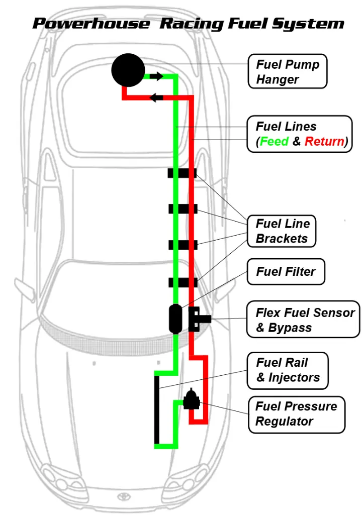
GENERAL FUEL SYSTEM LAYOUT
(Some locations, parts, or aspects may vary)
FUEL RAIL AND INJECTORS
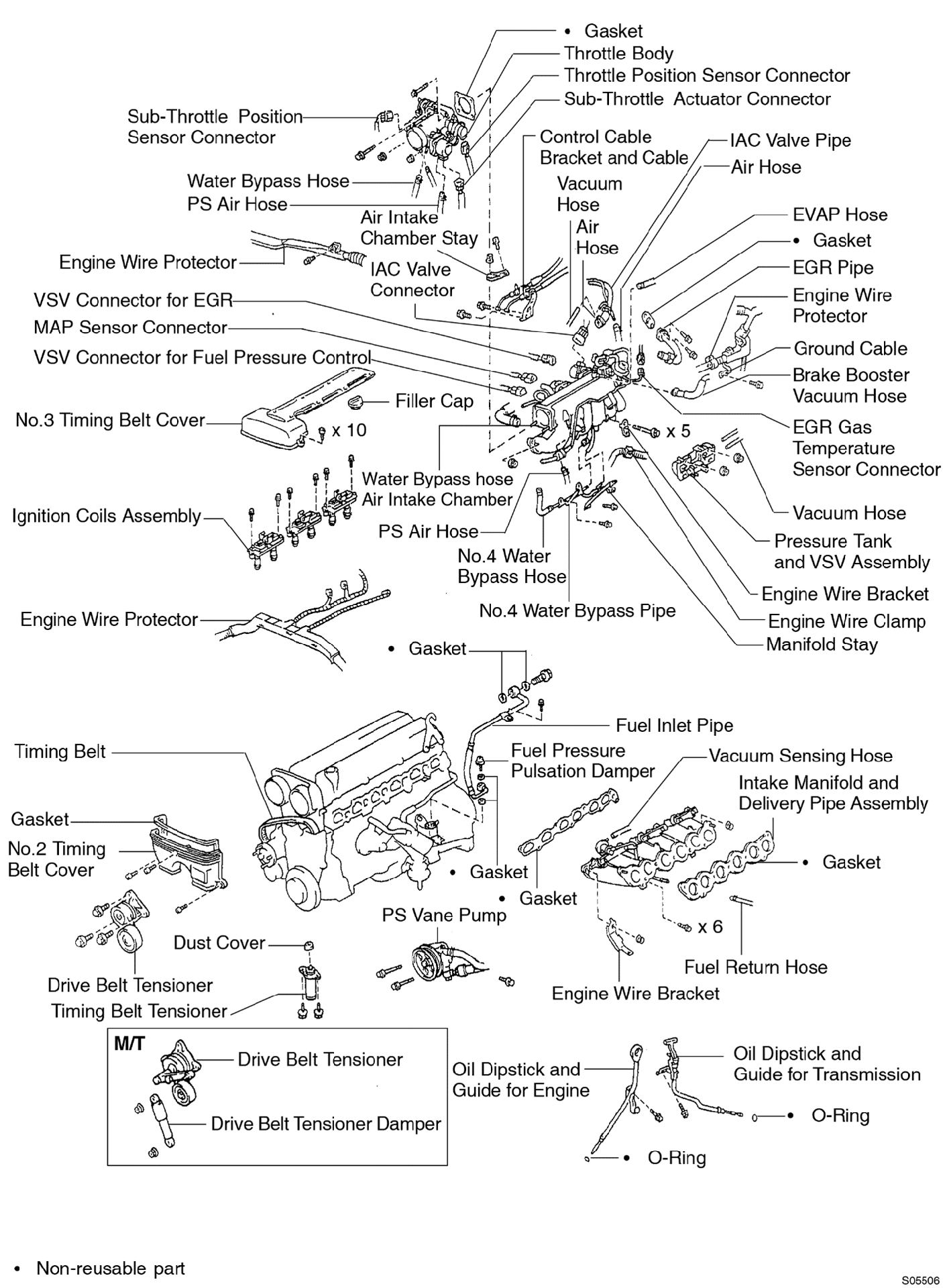
STEP 1 – Remove Upper Intake Manifold, Factory Fuel Rail. See factory service manual for details. If you are already running aftermarket intake, refer to manufacturer specific instructions.
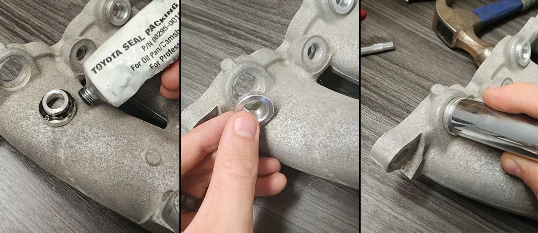
STEP 2 – Insert Fuel Injector Bungs, tap into recesses with a brass hammer or use a socket (size 15mm), taking care not to damage the bung or intake manifold. They are a light press fit and will bottom out in the recess. Tap lightly until firmly in place. You can choose to use a light amount of FIPG here especially if the bung is at all loose in the hole, but use sparingly, you do not want to impede the flow of the injector.
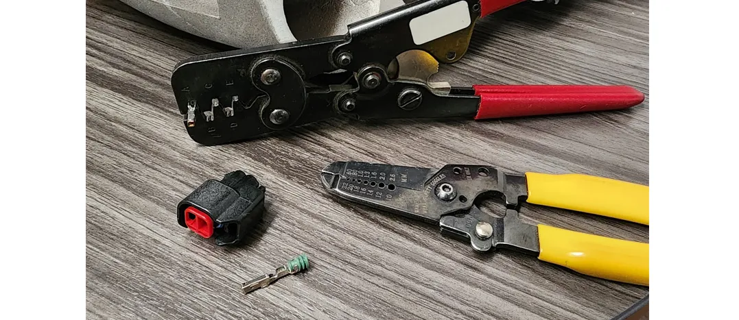
Step 3 – Install the ID injector connectors in place of the factory connectors. Polarity does not matter here. Strip existing wires, slide on wire seal, crimp terminal and slide into connector. If you have an aftermarket harness you can likely skip this step.
Step 4 – Assemble fuel rail: Attach brackets to rail using the supplied stainless socket-head bolts (3/16 allen head). Tighten until firm but do not tighten all the way. You should allow for some slight movement of the brackets until rail is in place with the injectors. Apply a small amount of WD-40 to the fuel rail fittings on the O-ring side. Install the fittings into the rail ends and Plug into the center of the rail with the o-ring side going into the rail. Tighten these fittings all the way. If you are using a dual feed system the return will be in the middle of the rail and feed from both ends.
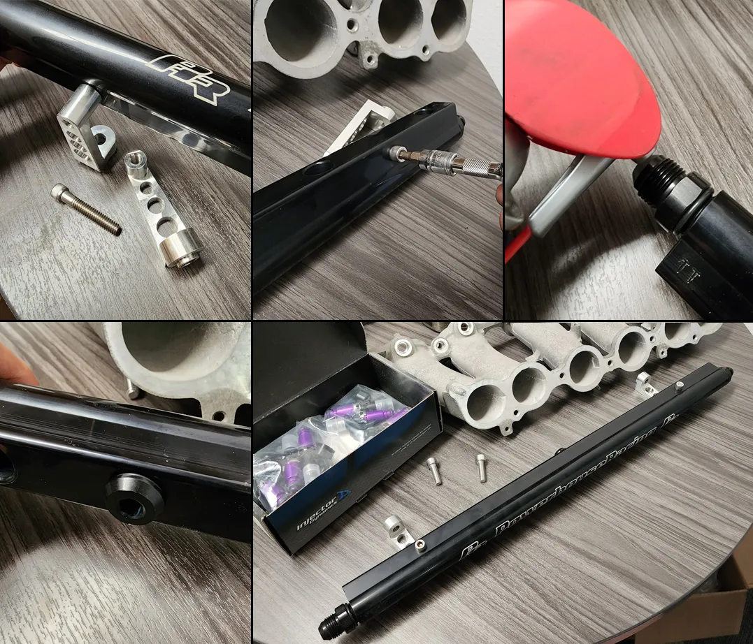
Step 5 - Lubricate injector o-rings and align brackets with manifold. Once all the injectors are into the bosses, tighten the brackets to the intake manifold using the 8mx1.25 socket-head bolts. A shallow or trimmed 5mm allen key helps tremendously. Make sure everything is aligned and use the m8 bolts to pull the injectors down into the bosses. Once bottomed out tightened the bracket to rail bolts (3/32 allen). All fittings and bolts should now be tight now. We would recommend some Loctite to make sure fuel rail stays safely in place
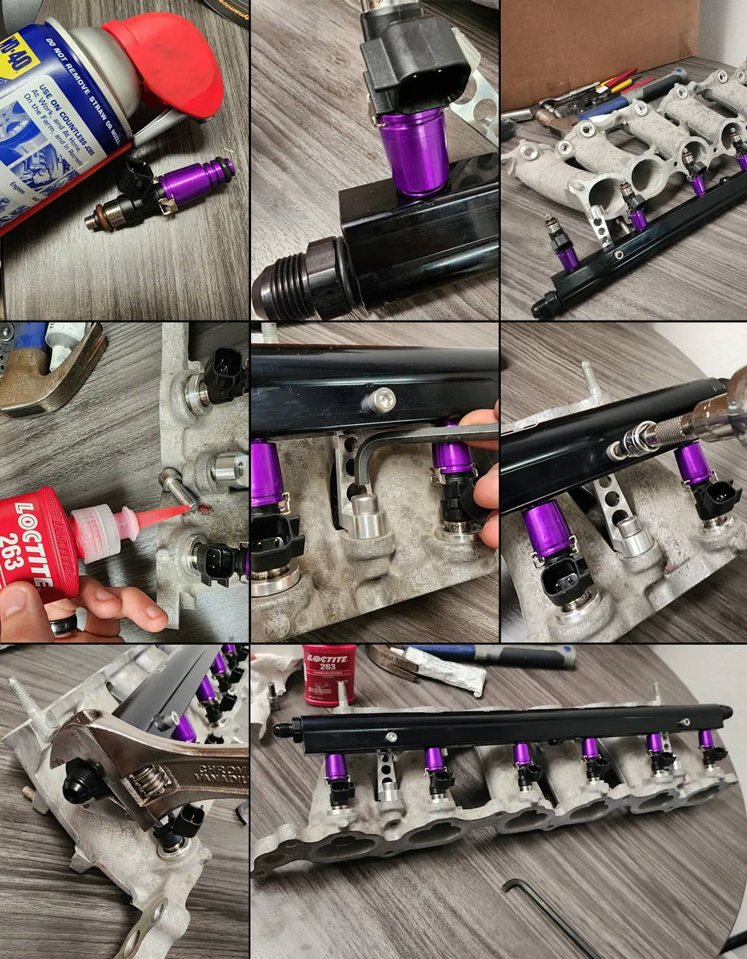
Step 6 – Install the Filter to Rail hose. The hose will attach on the firewall side of the rail. The 90 Degree hose end is the end you should be attaching to the rail and these should both point downward. Tighten it all the way. These should both swing under the car where they will attach to the filter. Be sure to keep clear of the steering column and any other moving parts or electrical contacts around the starter. Use zip ties for securing away from these.
Step 7 – Attach the injector clips to the injectors
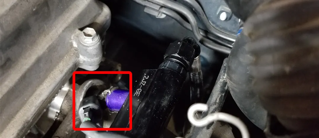
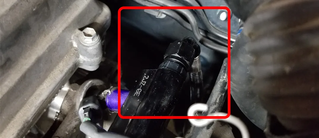
Step 8 – Reinstall the upper intake manifold. See the factory service manual for details. You can attach the front port (Rail to Regulator line) now or wait until later when you have the regulator mounted. (2JZ-GE Upper Plenum Pictured)

Step 9 – Remove Factory Fuel Hanger as well as the factory fuel line you have running along the car
Our friend, Ryan, over at Pure Function has put together a nice video guide for our Triple Fuel Pump Hanger. Please check it out here. Note he chooses to use DTM connections, that is optional.
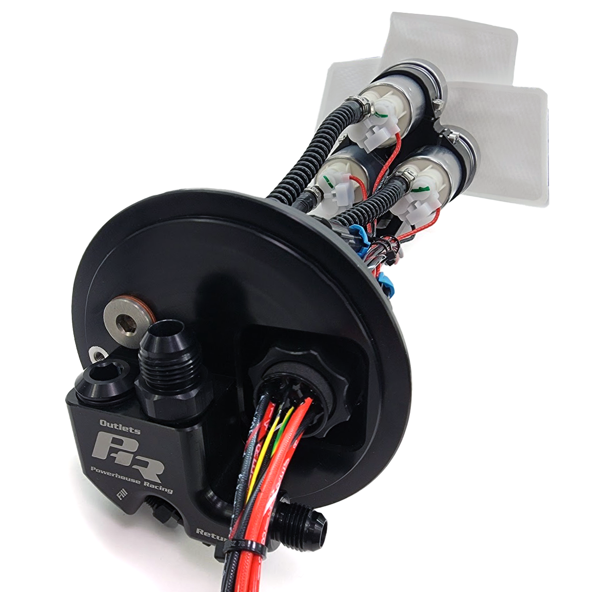
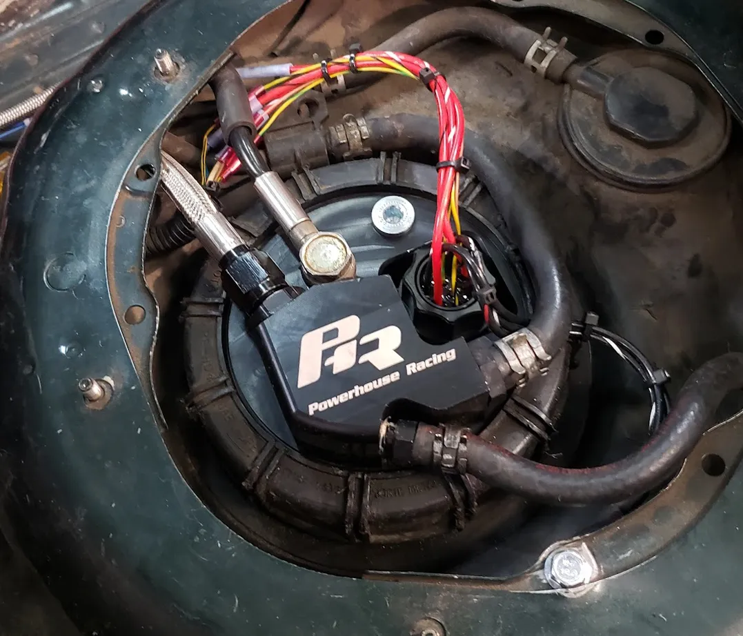
Step 10 – Install PHR fuel hanger assembly according to instructions above (this pictures contains some wiring and plumbing steps we will cover in later steps) Line configuration here uses oem feed and return lines along with an additional feed.
FEED LINE ROUTING
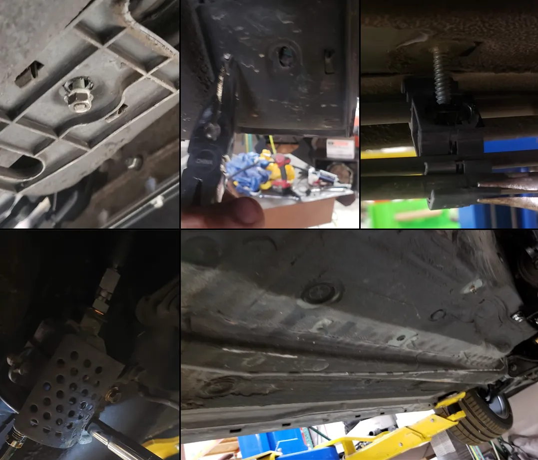
Step 11 – If you haven’t already, remove all factory fuel lines covers and factory fuel lines and filter. The plastic clips can be tricky. You can use a pair of pliers here to make your life a little easier. Sometimes the oem hardline can be difficult to remove from the oem filter, Use a wrench on both filter and line nut. As it loosens you may need to pull back on the line to keep from binding/twisting.
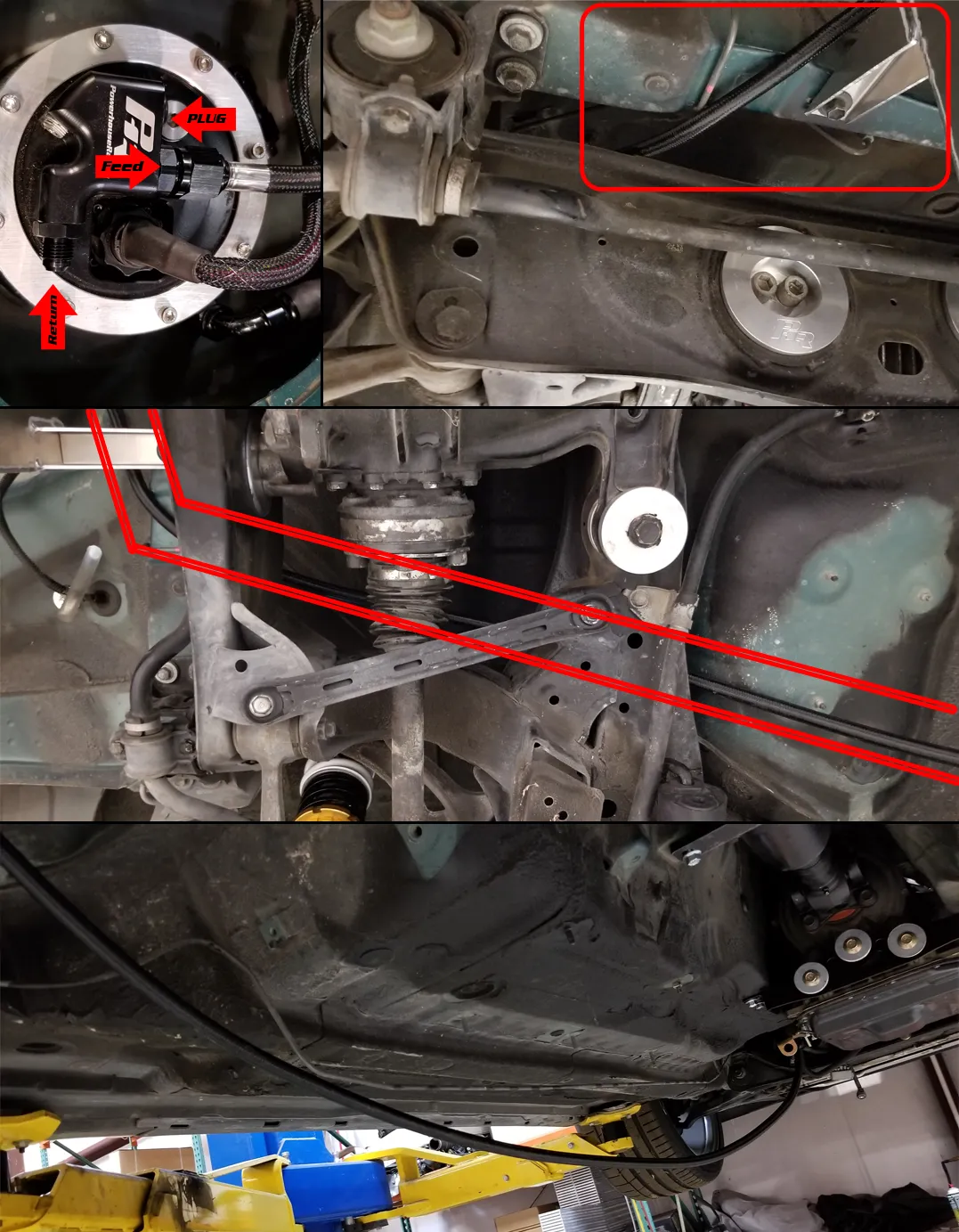
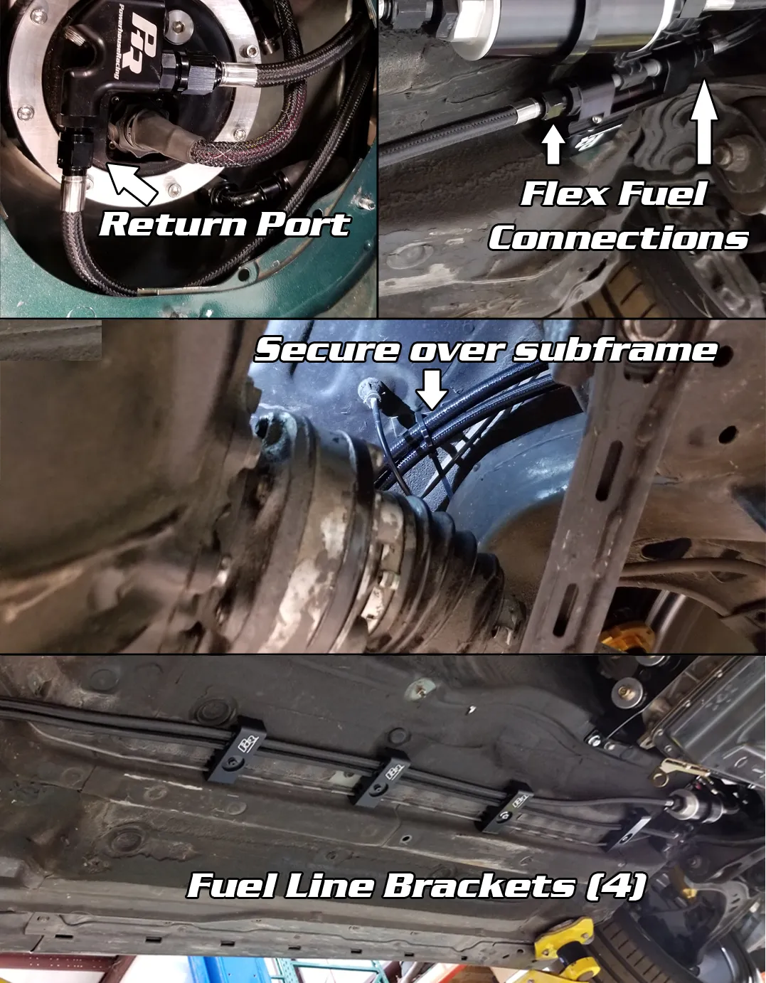
Step 12 – Run the stainless braided hose from your fuel hanger outlet to fuel filter location. Route along factory feed line. Use some zip ties here just to get everything held in place loosely. Start by feeding the line from up at your fuel hanger. Run it down until you can attach the hose end to the outlet on the fuel hanger. Either port can be used on a single line setup. Just make sure the opposite is plugged. The line(s) will route up over the rear subframe and follow the same routing as the oem lines. (see pictures)
Note:
This car is equipped with a PHR fuel cell, but all concepts and directions are
near identical
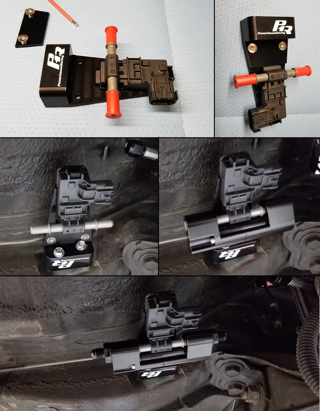
FLEX FUEL SENSOR
Step 13 – Let’s get our flex fuel sensor mounted in place. If you are utilizing the complete PHR flex fuel kit this is going to bolt in the factory fuel filter locations. Use lubrication on bypass o-ring and fittings orings. (See picture steps.). You can choose to wire in you flex sensor at this point, refer to your ecu manufacturer for wiring and calibrations support.
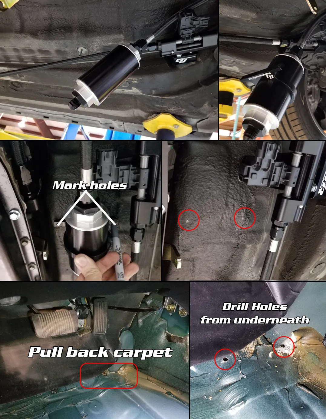
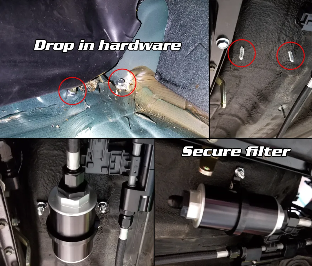
FUEL FILTER
Step
14 – Fuel Filter install can vary based on brand purchased. The split on the
feed line is going to be at the same location as the OEM fuel filter. In the
pictures below we are using the PHR Weldon Fuel filter bracket (single). We are
going to have to create our own holes for this. If you are using a goodridge or
similar small frame filter. There will be no bracket. It is light enough to be
supported by the fuel lines themselves. Make sure to measure twice, drill once.
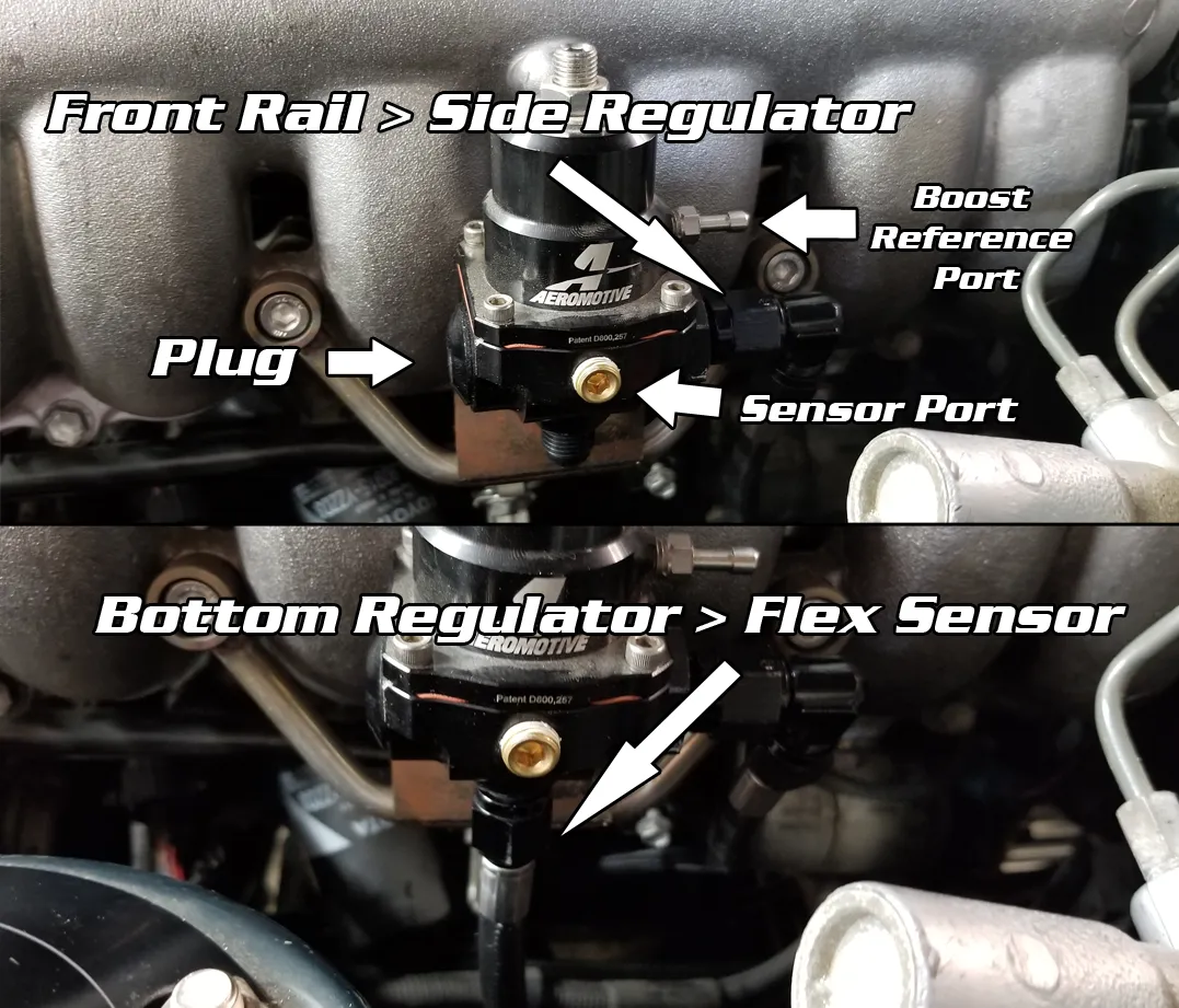
REGULATOR
Step 15 – Mounting your regulator can vary based on your intake manifold and line selection. If you are running OEM intake manifold, we have brackets that mount directly to the manifold near shock tower. If you are running an aftermarket intake manifold you will be utilizing our firewall bracket near brake booster (LHD). Use lubrication on regulator fittings o-rings. In a single feed or single rail line configuration you will be plugging one side of the regulator. You can now complete fuel line connection from rail (front port) to regulator (side port). As well as regulator (bottom port), run the line along the back of the firewall to later connect to flex fuel sensor (in port). You can choose to install your fuel pressure sensor at this point. Refer to ECU manufacturer for wiring and calibration support.
(Pictured is an GE intake manifold, the GTE Non-VVTi and GTE VVTi have very similar positioning)
RETURN LINE AND FUEL LINE HANGERS
Step 16 – Before going back under the car, attach your return line to your fuel hanger in the rear. Feed all the line through and follow the same pathing as the feed line. Once attached and tightened down at the fuel hanger you can work your way back to underneath the car. Finish connections on both sides of the flex fuel sensor. If you have purchased the fuel line hangers you can now install then and secure positioning on the routing of feed and return lines.
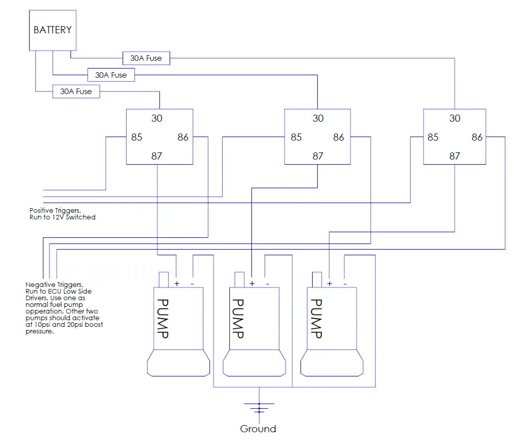
FUEL PUMP RELAY WIRING
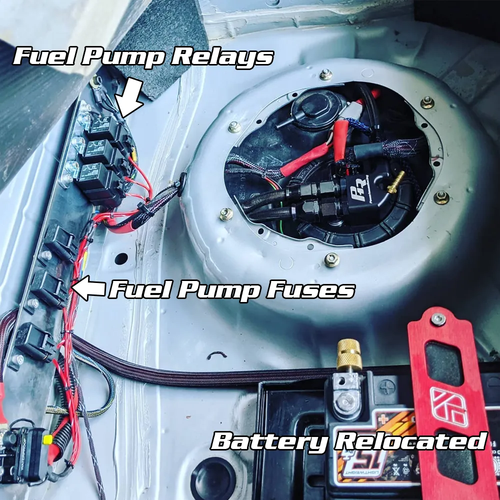
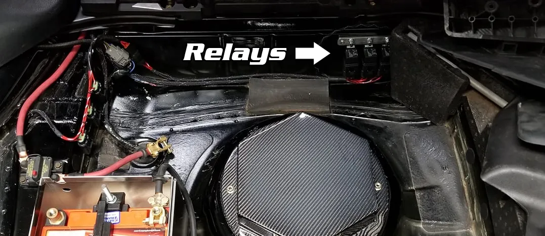
Step 17: Optional purchase (PHR Relay Wiring Harness). The harness has some flexibility as far as mounting location. We typically recommend installing the relay bracket in front of the spare tire well. You can drill and tap your own mounting holes here, or some customers choose to build they own mounting plate. (see picture)
Power/Battery Location: If it’s still in the front of the car, the power leads (fuse side) will run through the driver side(lhd) area through the firewall bulkhead near the brake booster. You can mount the fuses near the fuse box and attach the power eyelet to the battery directly or to the large power stud on the bottom of the fusebox. The fuel pump side of the harness can be attached to our fuel hanger connector (red wires). Recommend using appropriate size butt connector and shrink tubing here. This connector is removable if you untwist the cap.
If you have relocated battery to the rear you can either coil up the excess wire lead or trim the harness down. In that case you can mount the fuse holders on the same surface as the relays.
(see picture)
Ground Location: When choosing a ground location be
sure to remove any paint from the surface. You want it to be bare metal and
have a solid contact. Uses an eyelet to crimp ground wires together and make
easy work of attaching to chassis ground.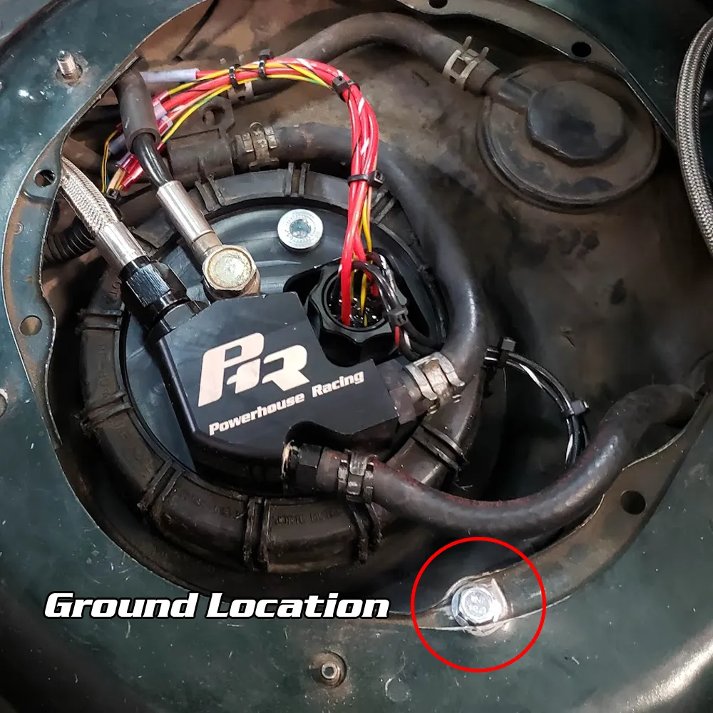
Trigger Wires: Depending on your ECU you may want to trigger in one of two different ways:
NEGATIVE TRIGGER
If triggering from Low Side Drivers from your ecu, wire the small gauge red wires to a 12v switched source. Run the small gauge black wires each to its own Low Side Driver at the ECU. Use the ECU to control the fuel pumps.
POSITIVE TRIGGER
If triggering from High Side Drivers from your ecu, wire the small gauge black wires to ground. Run the small gauge red wires each to its own High Side Driver at the ECU. Use the ECU to control the fuel pumps.
The functionality should be as such:
One pump should be run like a normal fuel pump. It should be activated for priming and for vehicle running and everyday driving.
The second and third pumps should be staged to activate at increasing boost pressures. Generally, these are controlled using a general output or auxiliary output.
Once power is connected to the vehicle, prime the fuel pumps and check for any leaks. Keep in mind that you will need a basemap to start the car following installation and a tune before any driving can be done under power.
Thank you for using our guide, if you have any additional questions, feedback, or tips/pictures you’d like to share with us please email them over to websales@powerhouseracing.com