PHR Cold Side Intercooler Pipe
Please note: PHR 3.0" Cold Side Intercooler Pipes are designed for use with the OEM clutch fan setup, OEM 2JZ-GTE intake manifolds, and PHR 4.5, 5 and 6 inch intercoolers. We cannot guarantee fitment if you are using a different fan setup, different intake manifold, or different intercooler. Please also note, just like any front mount intercooler setup, the AC line brackets will have to be detached and moved underneath the piping.
These instructions include the following items:
- PHR 3.0" Cold Side Intercooler Pipe Kit (includes worm clamps and silicone couplers)
- Tial Q Blow Off Valve
- 40 inches of 1/4in vacuum hose
- 1/4in vacuum tee
Step 1:
On left side remove a/c line to frame rail mounting bolts and lower the line down for easier access.
Step 2:
Using a large pair of vice grip pliers clamp down on the a/c line fittings so that you may remove there mounting brackets without releasing/discharging the a/c system.
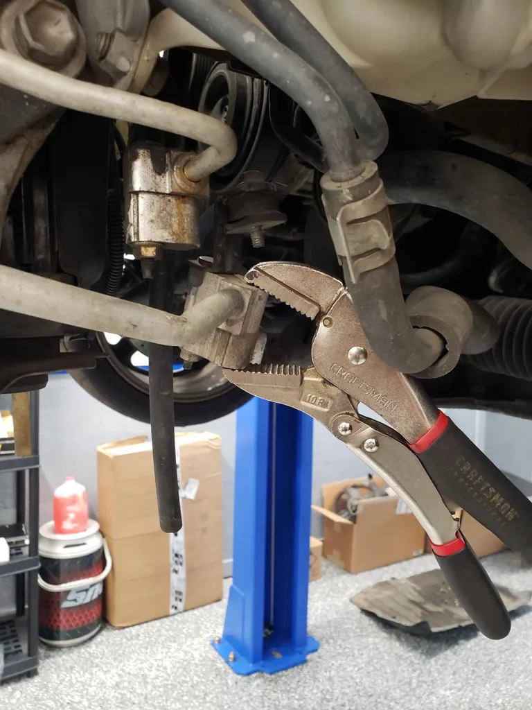
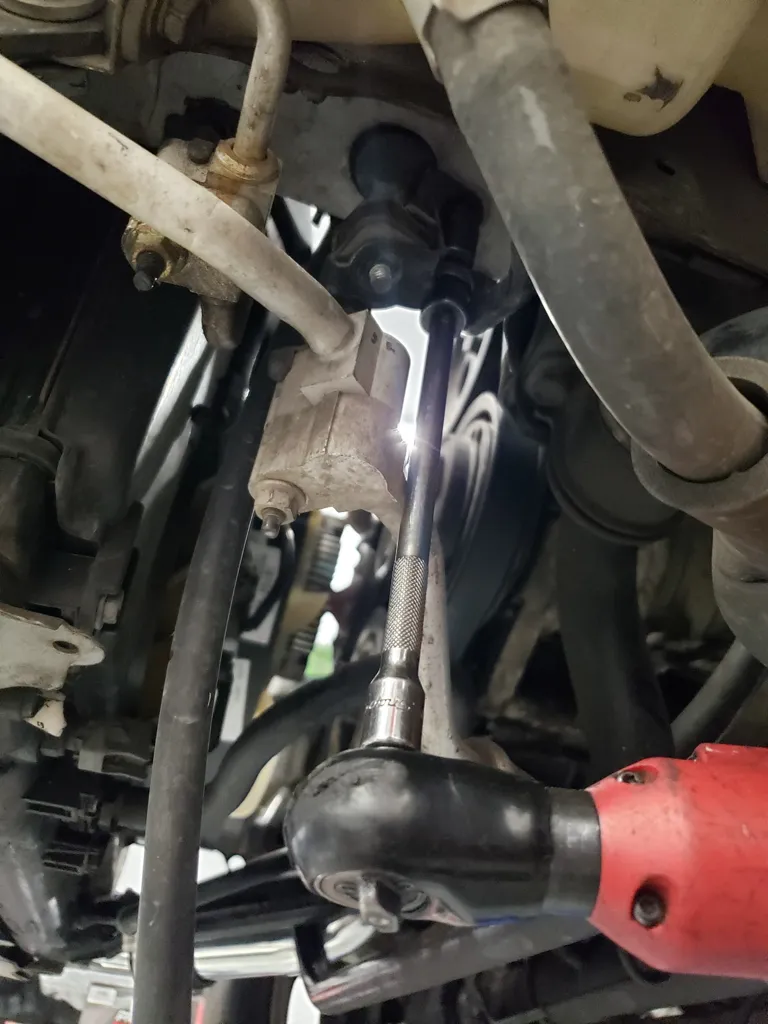
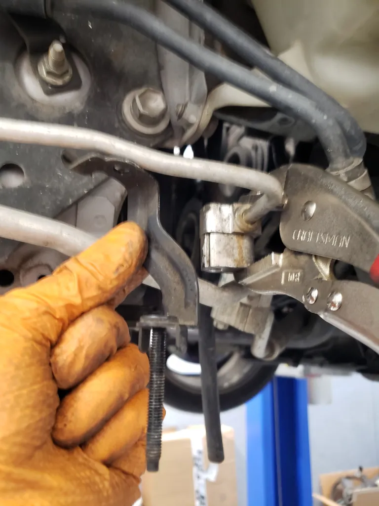
Step 3:
While clamped in the vice grips remove the factory m6 nut and mounting bracket. Then install the M6 bolt acquired in previous step along with factory M6 flange nut and tighten.
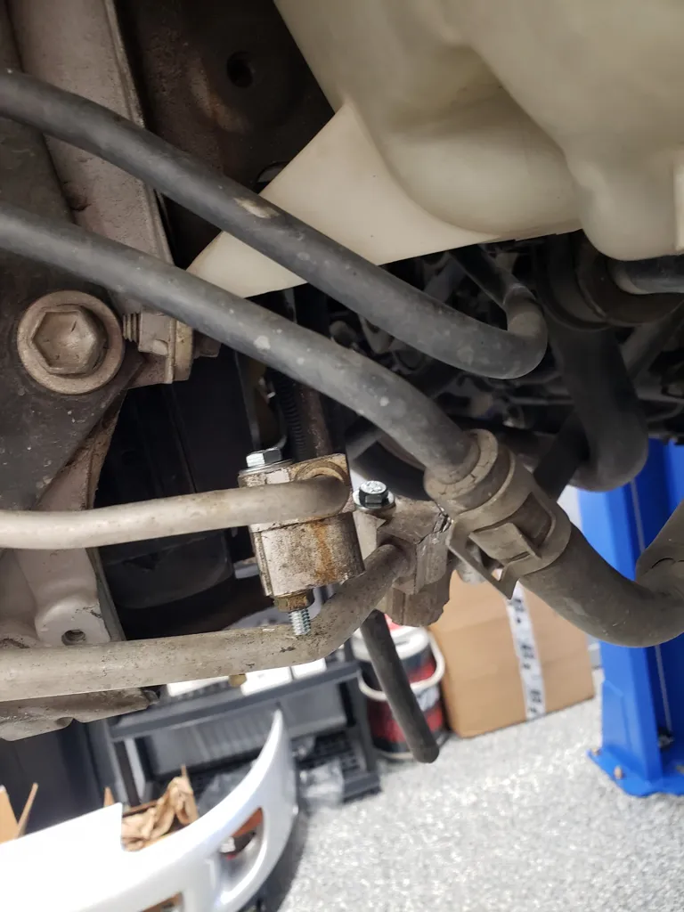
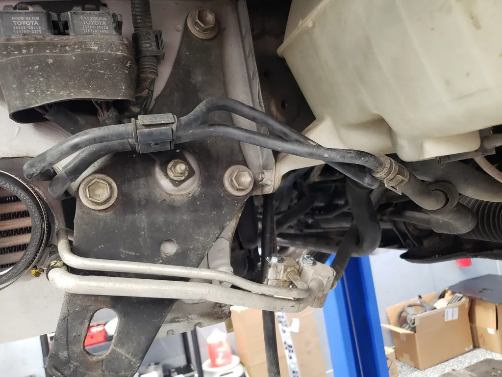
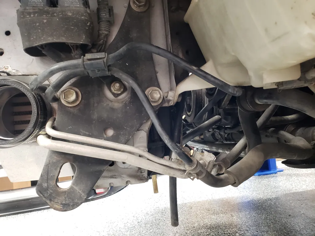
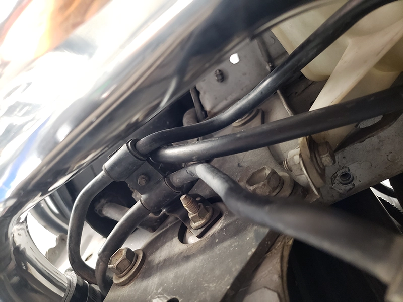
Step 4:
Remove vice grip pliers and repeat on the other a/c line. below is a view of M6 bolts installed and factory a/c line mounting brackets removed.
Step 5:
Gently bend a/c lines down to gain clearance for charge pipes.
Step 6:
Depending on your model year of Supra as well as whether its auto or manual transmission you may have a radiator fan connector that needs to be repositioned for clearance. Remove it with its mounting clip from the radiator fan bracket
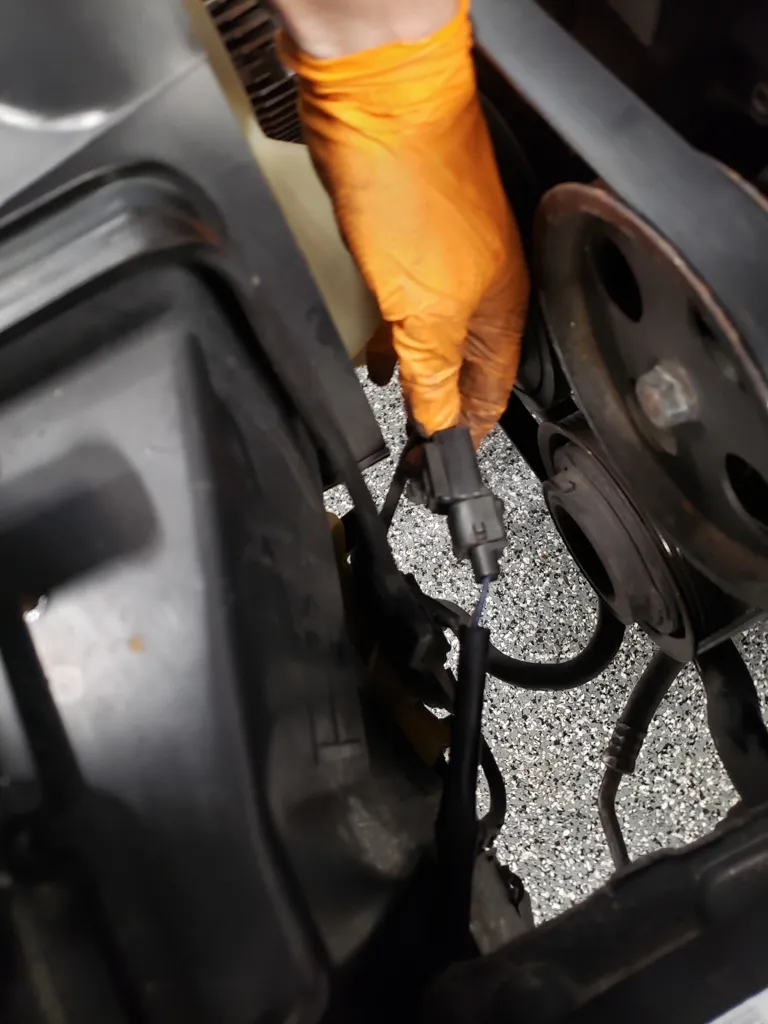
Step 7:
Remove the top mounting bolt of the radiator fan bracket and move fan bracket slightly to slip fan electrical connector onto opposite side of fan bracket and re clip in place using same clip hole in bracket. Reinstall top mounting bolt of fan bracket. If additional clearance is required in the following steps some grinding/material removal of the factory radiator fan bracket my be required.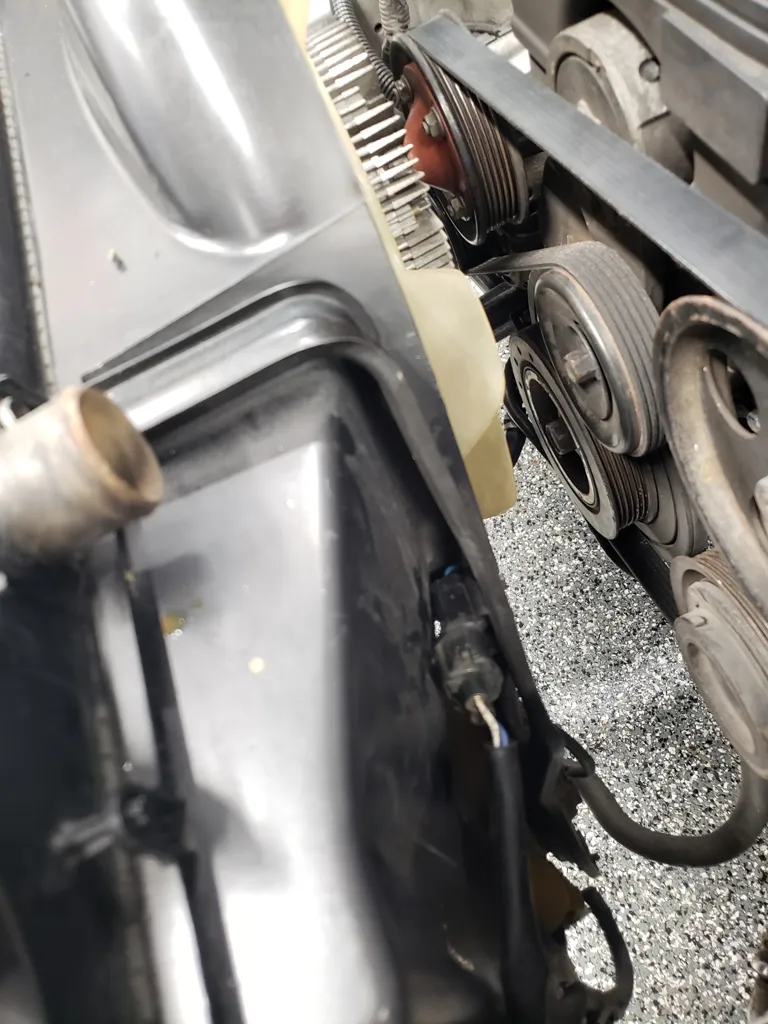
Step 8:
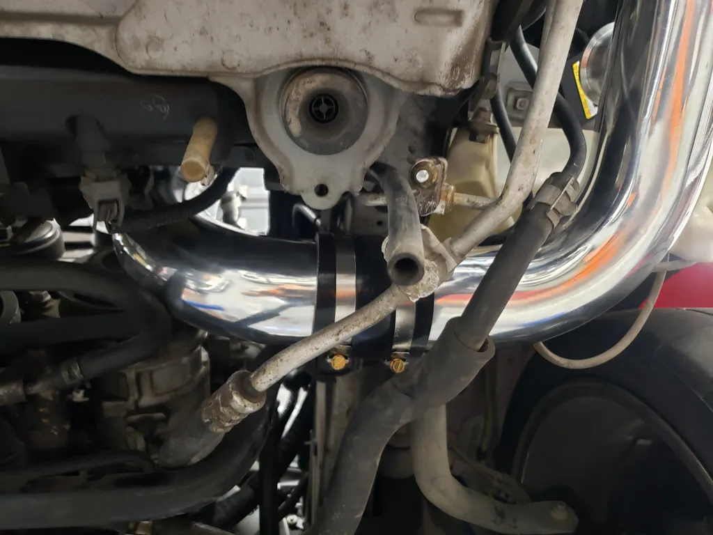
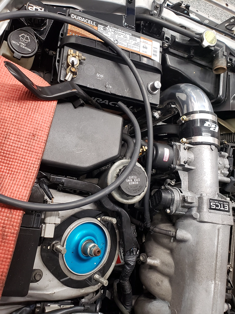
Gently route/bend the lower of the 2 power steering lines down for charge pipe clearance.
Step 9:
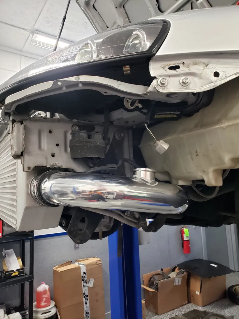
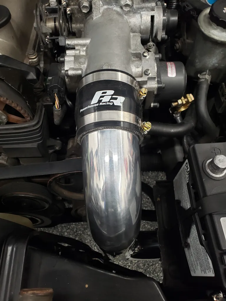
Loosely install throttle body inlet pipe and coupler onto throttle body. Check for clearance issues all around the pipe.
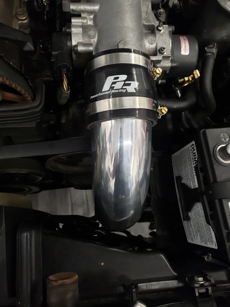
Step 10:
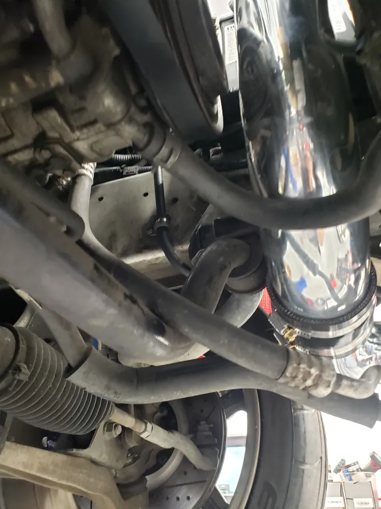
Install intercooler outlet pipe to throttle body inlet pipe then into coupler on intercooler outlet.
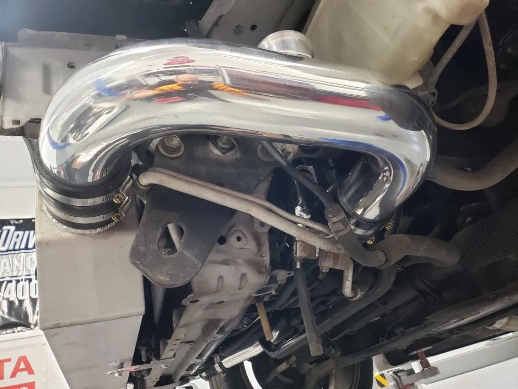
Step 11:
check and adjust for clearance between lines, charge pipes, and frame rail so that adequate clearance is had by all components and that no contact is made between any of them.
Step 12:
begin to tighten all 6 clamps starting at throttle body inlet coupler, while double checking for adequate clearance all around throttle body inly pipe. Adjust and recheck as necessary.
Step 13:
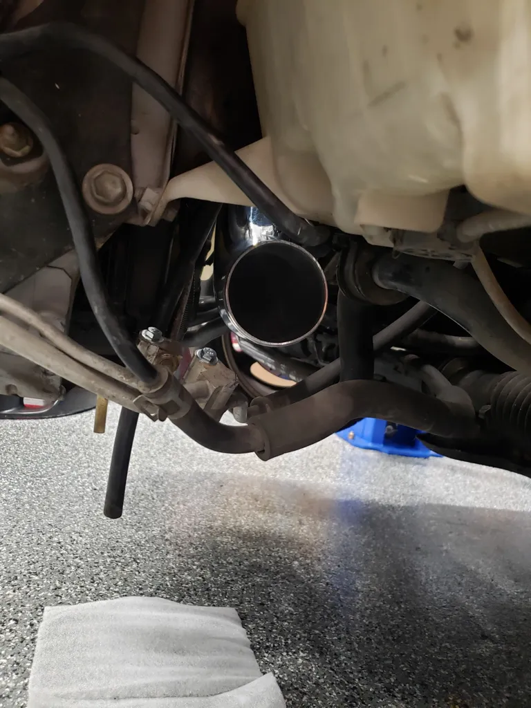
Preassemble BOV as needed per BOV manufacturer instructions based on engine idle vacuum. Some BOVs come with different springs while others have adjustment spring spacers. Most healthy 2JZGTE (non-vvti) engines produce about 20(+/-2) inches of vacuum at idle. Once properly assembled install BOV onto intercooler outlet pipe BOV flange. Make sure the O-ring seal is properly installed between the BOV and the flange.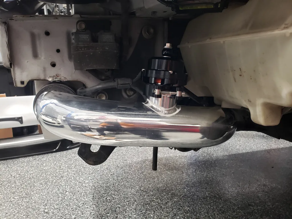
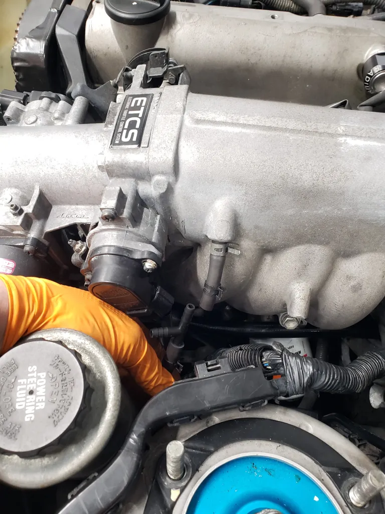
Step 14:
Cut and install a 1/4in vacuum tee into factory power steering idle up switch vacuum line. If power steering idle up switch has been disabled skip this step. (Use 10 x 10mm hose clamps on all 1/4in vacuum connections to ensure no leaks with develop(especially at high boost)
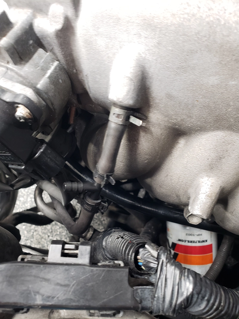
Step 15:
Measure and cut a 36in section of 1/4in vacuum hose if not supplied in kit and install onto tee from previous step
Step 16:
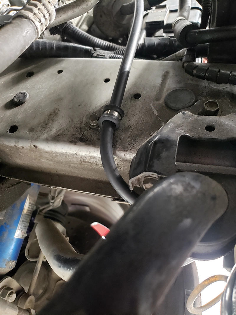
Route vacuum line down frame rail and over sway bar,
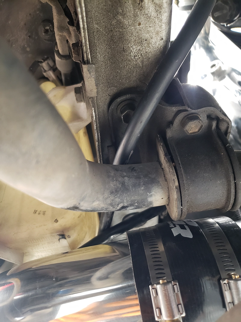
Step 17:
then route vacuum line down under the windshield washer reservoir and up towards BOV
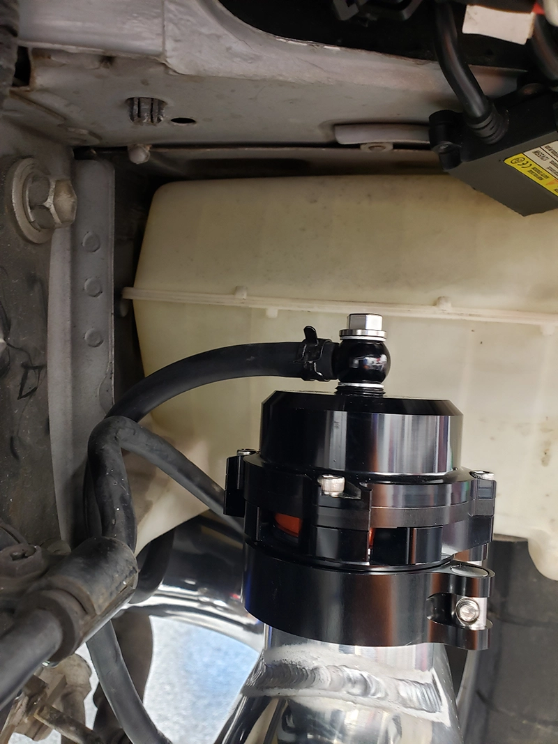
Step 18:
Install vacuum hose onto BOV vacuum port and rotate BOV vacuum port until adequate position is found, then tighten BOV vacuum port banjo fitting
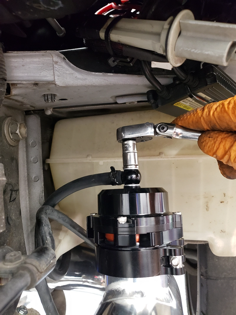
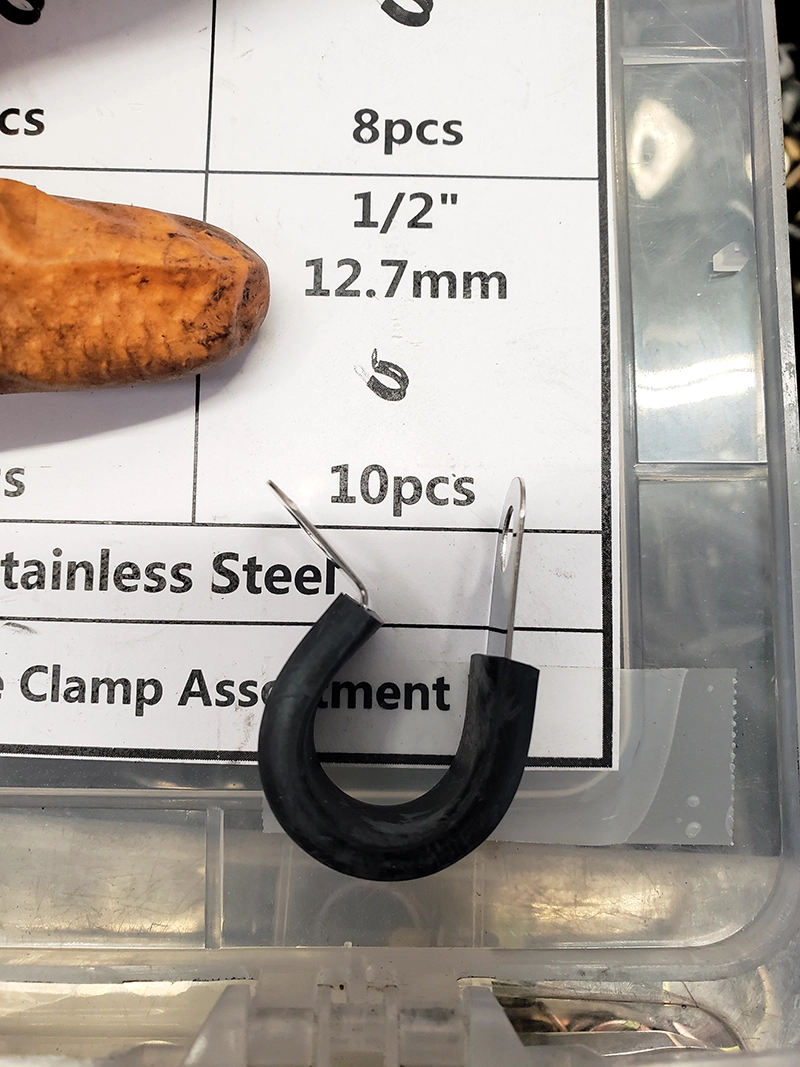
Step 19:
Install a 1/2in cushioned p-clamp (should be provided) around BOV vacuum hose and onto left side frame rail using an M6 bolt that was removed from the a/c line mounting brackets in previous step. An existing m6 threaded hole is used on left side frame rail.