This is a comprehensive installation and setup guide for the ultimate cooling fan solution for the 1993-1998 Toyota Supra. Keep in mind that this shroud requires you to relocate your battery. Additionally, the cold side intercooler piping must route through the battery tray location.
Step 1: Disconnect your battery. Drain some coolant, enough to remove your upper radiator piping. In addition to the piping remove your factory clutch fan setup and shroud. Remove your intercooler piping if necessary.
Step 2: Drop in the PHR fan shroud, there will be 4 tabs you will connect to your radiator with included m6x1.0 hardware. The top bracket, on turbo exhaust side will need a spacer and the longer bolt. Make sure wiring is fed up through the space between shroud and framerail.

Step 3: With shroud in place it’s time to start connecting your fan harness. Start by positioning your fuse holder provided with the kit. I recommend finding an appropriate spot for the fuse holder. This can go on the top or the side of the frame rail, the position is flexible within the reach of the power wire from the fans. This can go on the top or the side of the frame rail. There are self-tapping screws provided. It will be helpful to use a smaller drill bit to start the hole.

Step 4: With the fuseholder in place. You can now start to connect the provided eyelets

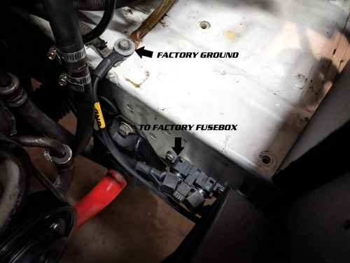
Take the thick, 4g wire and connect to opposing side of fuseholder, this will run to your fuse box,
one you have the wires positioned to your liking, tighten the nuts on holder and on fusebox.

The ground wire will attach to the factory ground location on the frame rails (see picture).
-------------------------------------------------------------------------------------------------------------------------------------
Step 5: You’ve been provided with a two wire extension harness, this is to be run to your ECU, most commonly found in passenger footwell. Normally we will run these wires in front of radiator behind the headlight, up along passenger side harness, through the firewall by your main factory harness (ignore the colors in this picture)

Note: Your wires will be yellow and white, picture just depicts firewall passthrough location
White Wire – PWM Output Connection (pin location is dependent on your ecu, if you are unsure which output to use please contact your tuner)
Yellow Wire – 12v Pullup Wire (may not be necessary if your ecu has built in pull-up protection on it’s outputs) , if it does not or you are unsure, please connect to a 12v key-on source.
Setting up your ECU:
The fantastic part about these fans is it give you complete control over the speed versus temperature. Please be aware the duty cycle is reverse of what you may logically think.
ECU Settings | |
Hertz (Hz) | 120 |
High (Full) Speed | 10% DC |
Low (Turn On) Speed | 80% DC |
Note: If you have the ability to invert your output then your high speed and low speed values can swap
!!!WARNING!!! DUTY CYCLES LOWER THAN 10% or HIGHER THAN 90% WILL TURN FANS OFF. PLEASE TEST FULL OPERATION WINDOW SO YOU DO NOT HAVE FANS TURNING OFF AT POSSIBLE CRITICAL TEMPERATURES.
Examples:


If you have additional question please reach out on our technical support line 817-238-8434 ext. 3 or email us at websales@powerhouseracing.com