these instructions include the following products:
- 4.5" intercooler
- hot and cold side intercooler pipes
- Tial Q Blow Off Valve (BOV)
- 40 inches of 1/4in vacuum hose
- 1/4in vacuum tee
- assorted worm clamps and silicone couplers
Step 1:
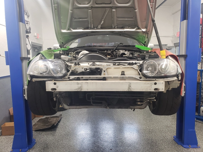
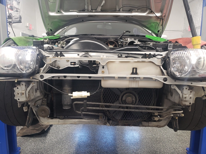
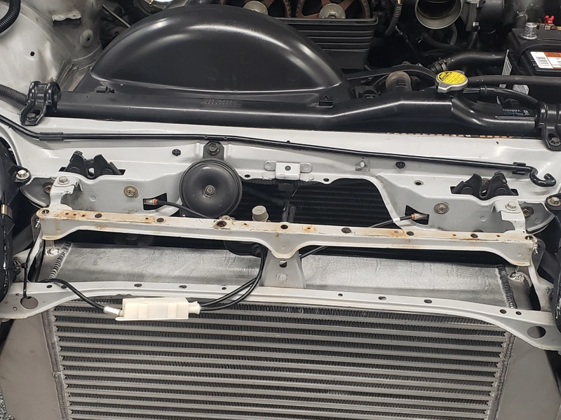
refer to the Toyota workshop manual to remove the front bumper cover (not shown), front crash bar, plastic air diverter trim panel, and the OE Coolant overflow reservoir, power steering line mounting bolts, and OE condenser fan.

Step 2:
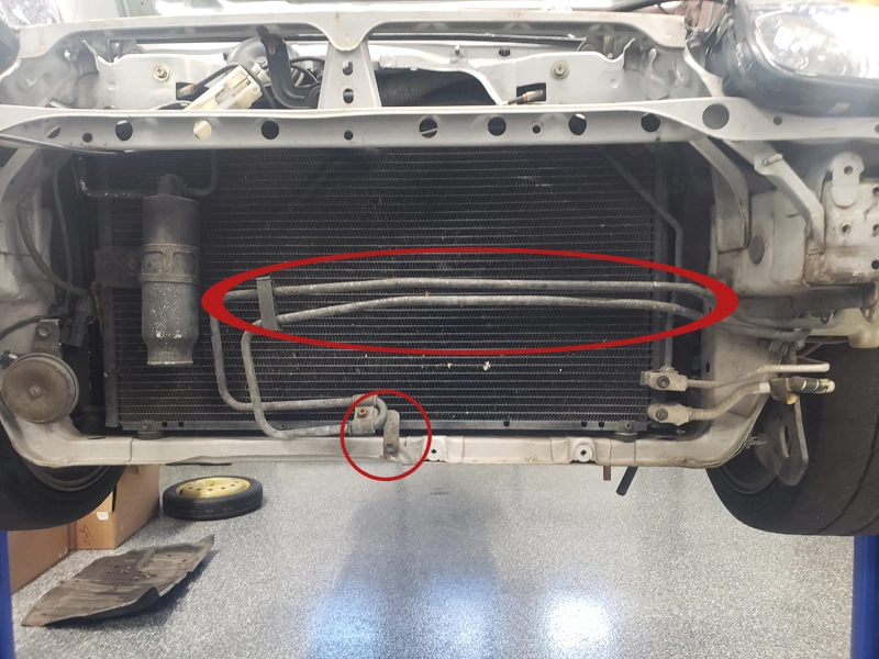
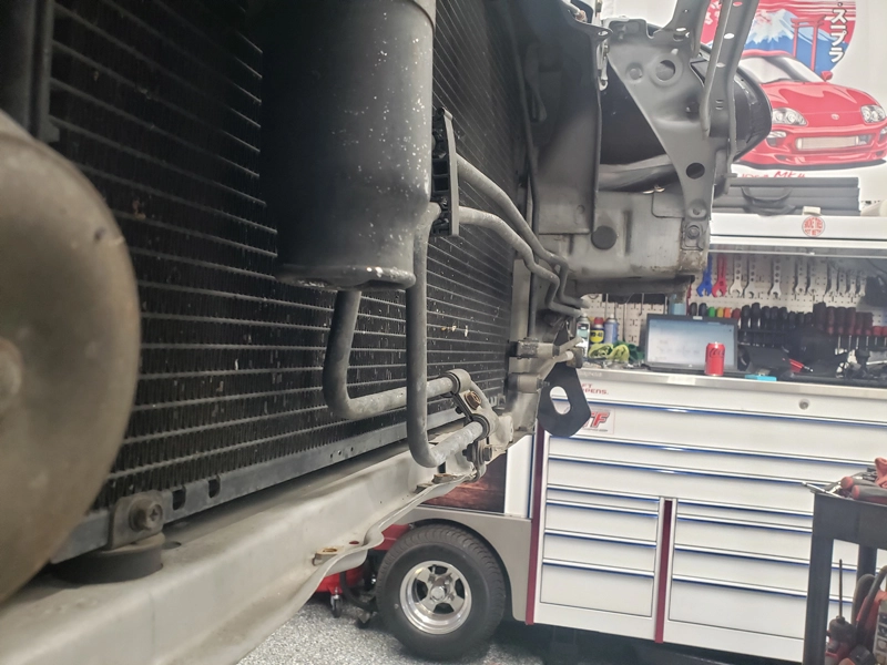
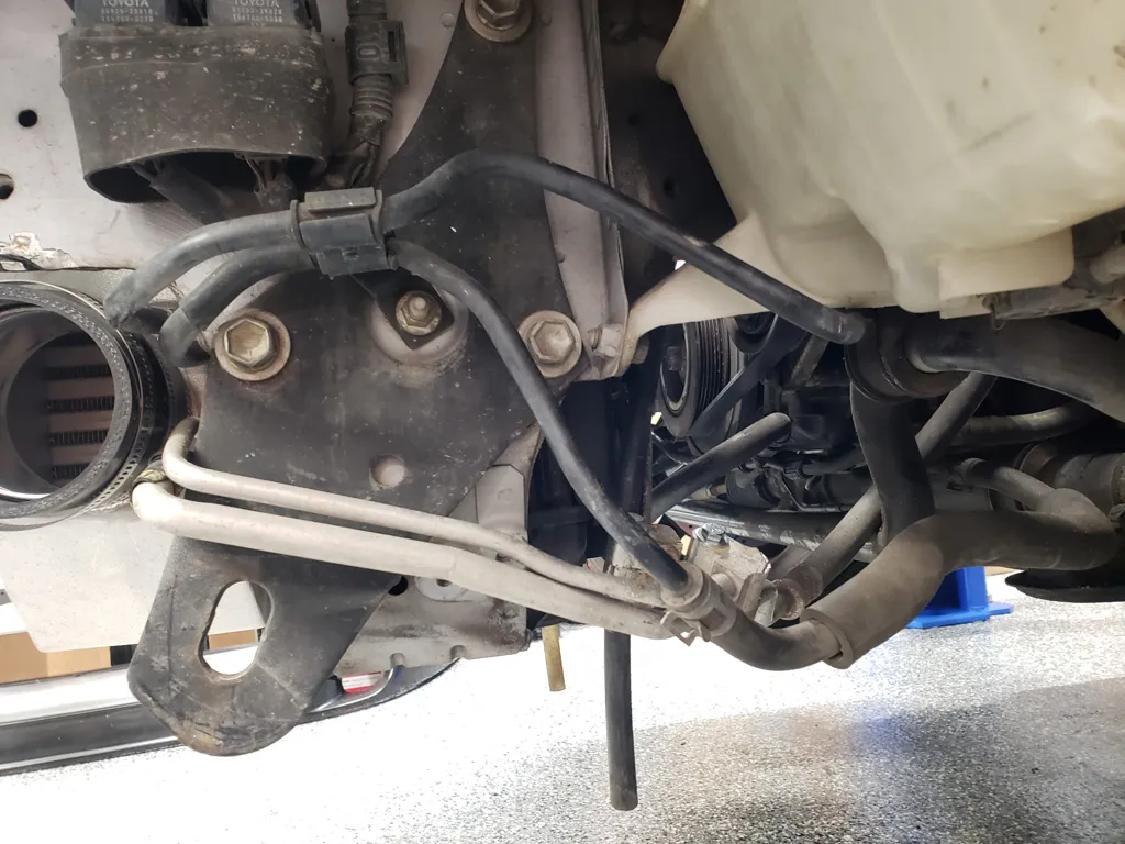
Reinstall power steering mounting bolts and gently bend power steering lines towards a/c condenser to make clearance for intercooler.
Step 3:
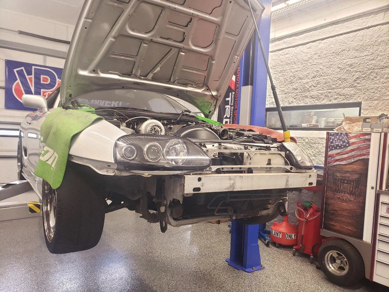
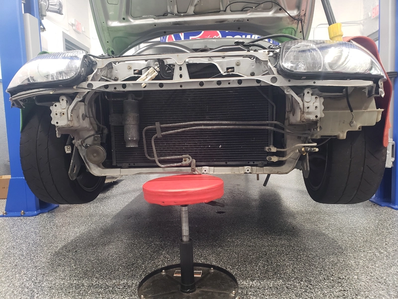
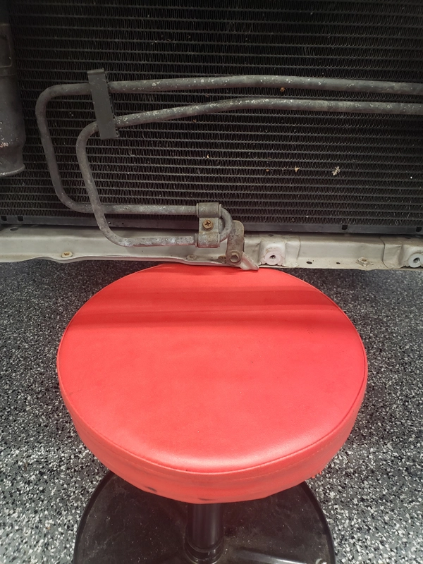
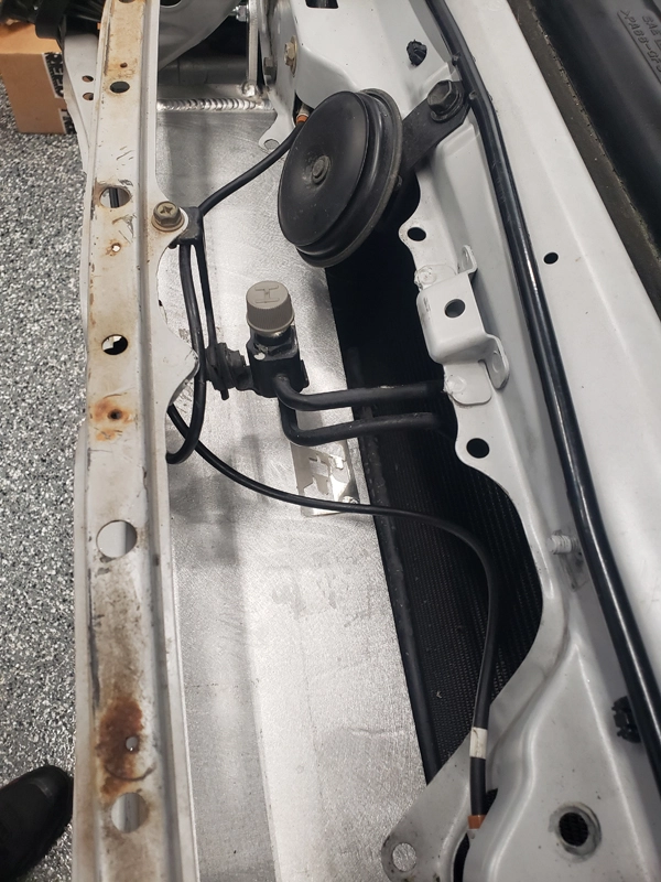
Find and position something suitable to support the new intercooler for install (detailing seat shown) and set the intercooler onto your support positioned in previous step.
Step 4:
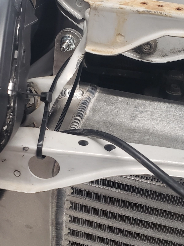
Using a tie strap, temporarily move and strap the hood release cable up and away from intercooler so that it will not be in the way or become pinched by intercooler during install.
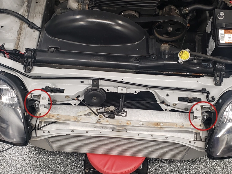
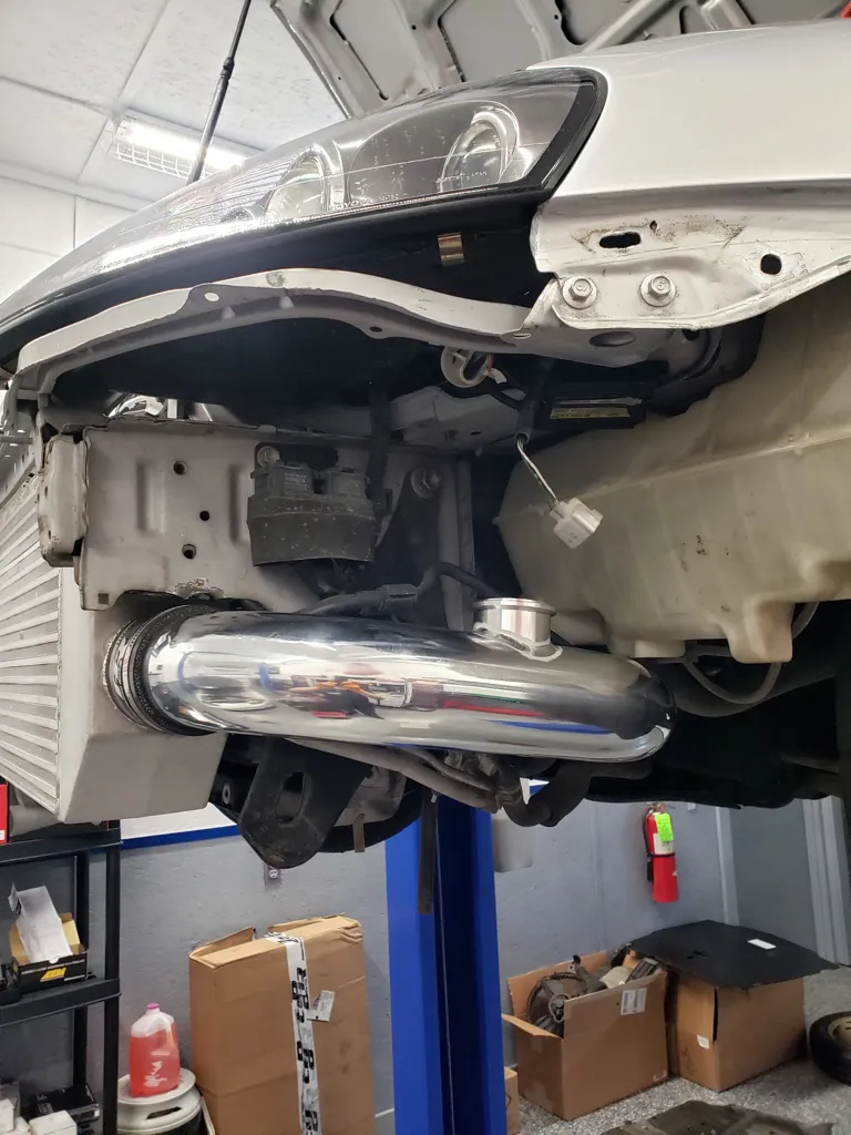
Step 5:
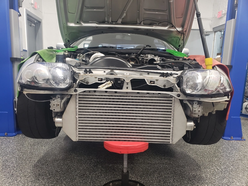
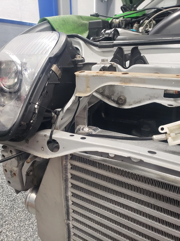
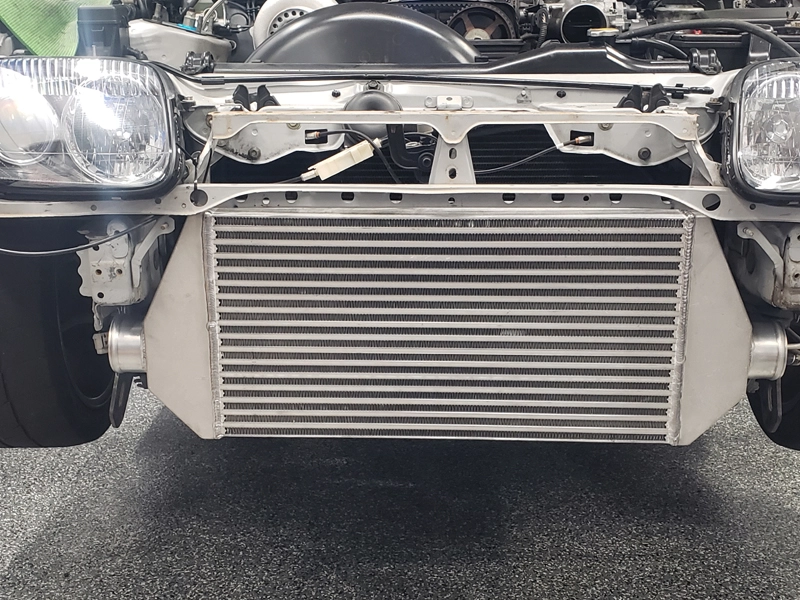
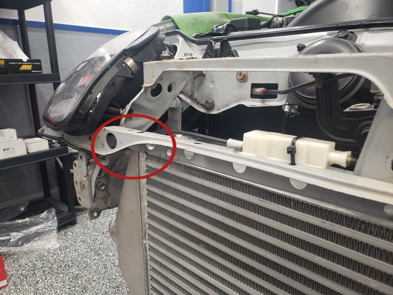
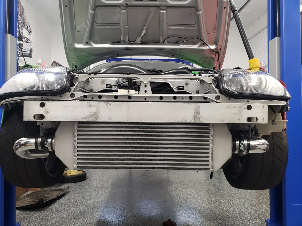
Move intercooler into position and align mounting tab holes with the existing holes in radiator support below hood latches.

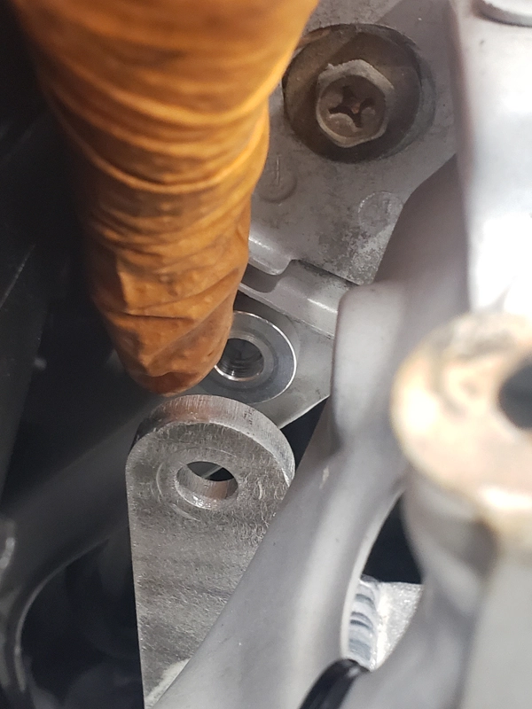
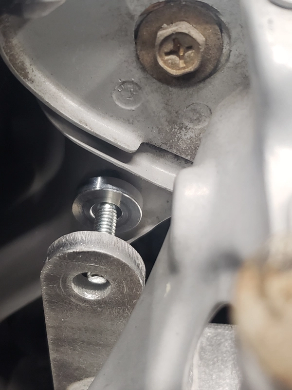
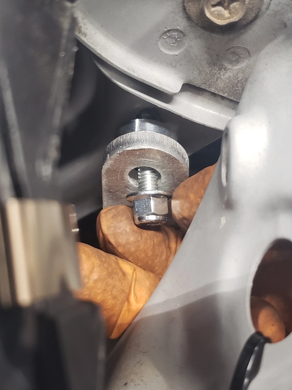
Step 6:
while holding supplied intercooler mount spacer in place, install the supplied M6 bolt of appropriate length. Then slide intercooler onto mounting bolt and loosely screw on the M6 locking nut. do for both sides.
(Upper mounting bolt size: M6 - 1.0 x 30 Cap Screw)
Step 7:
Remove whatever support you are using, and allow inter cooler to hang from M6 mounting bolts installed during previous step.
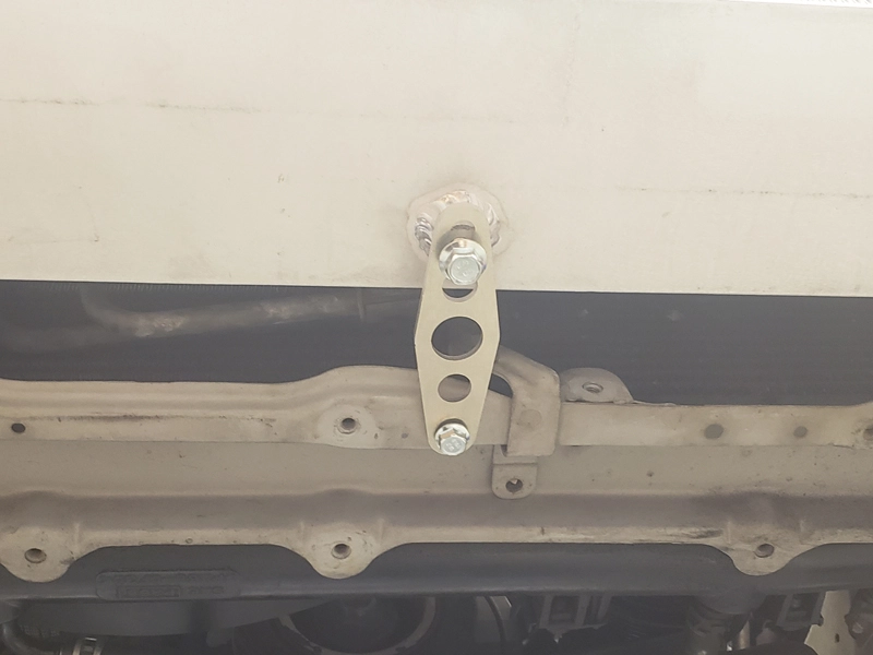
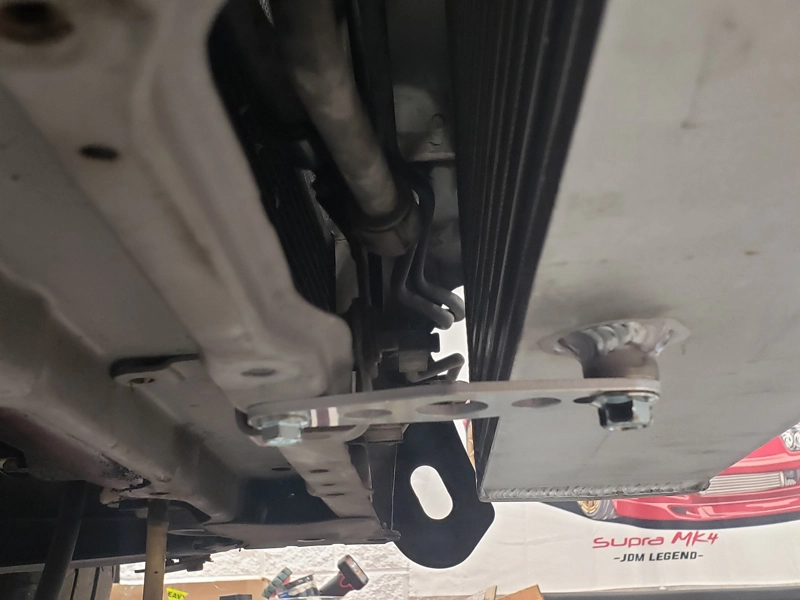
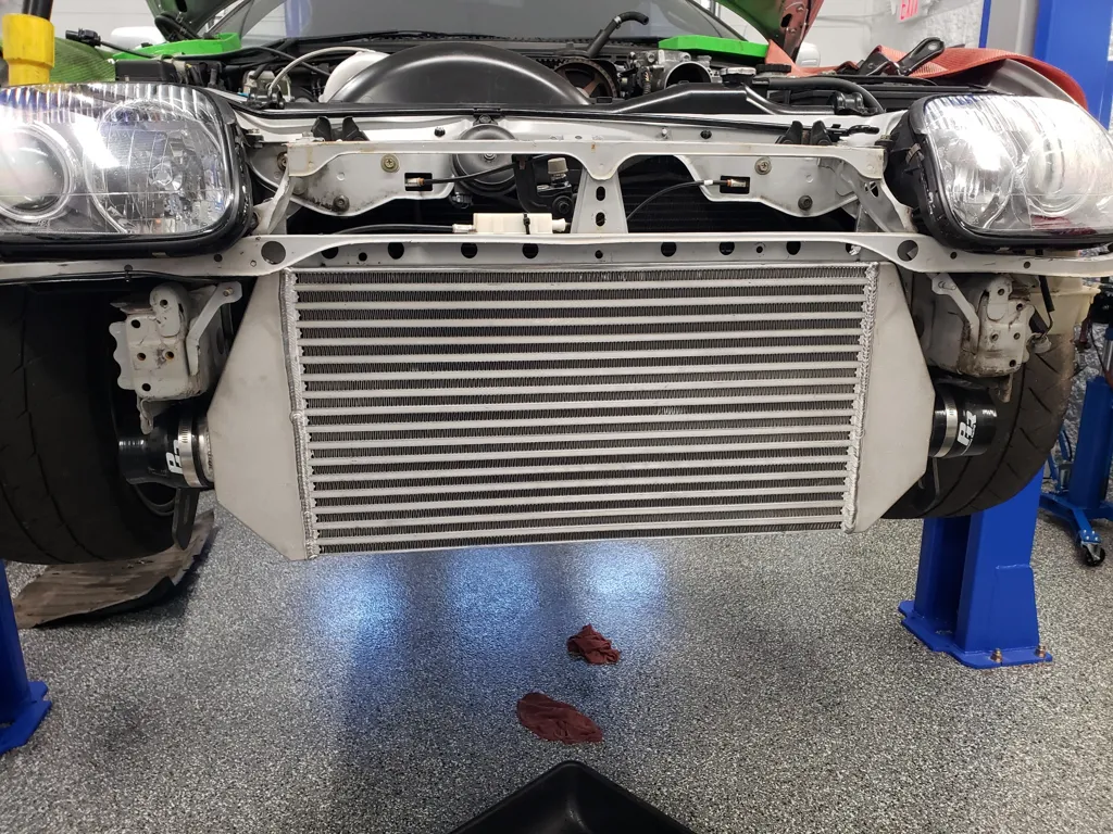
Step 8:
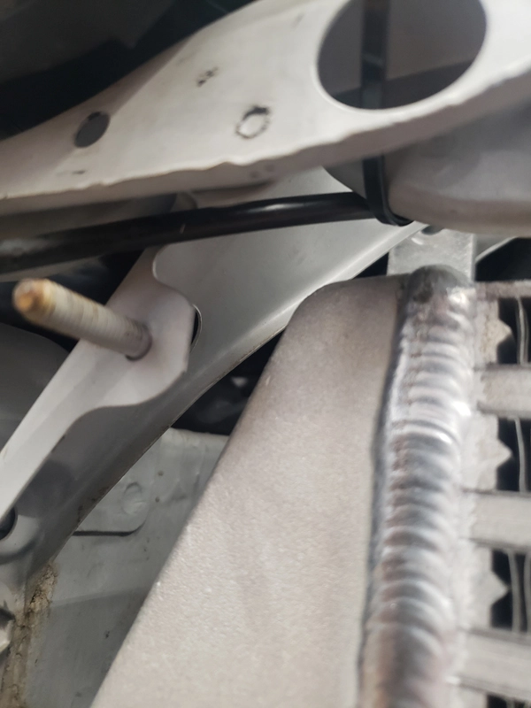
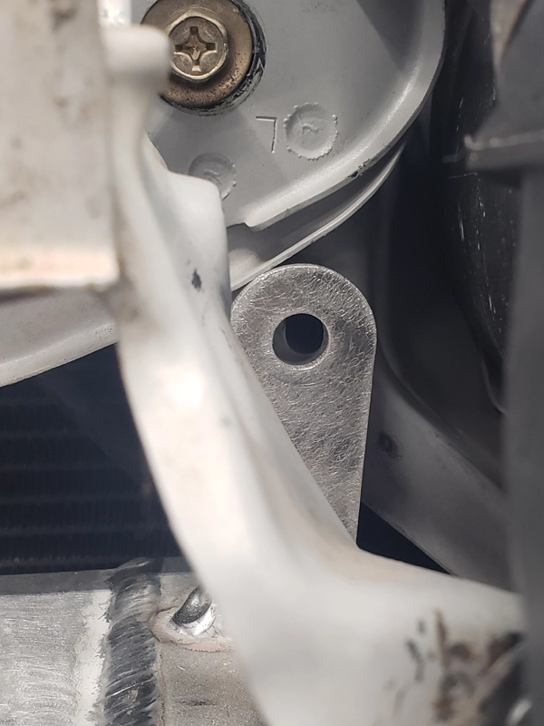
Loosely install lower intercooler support bracket using supplied bolts and push/pull intercooler into position so that it is not tilted inwards or outwards, but rather straight up and down. use a leveling device to make an more accurate position. once intercooler is in the desired position, tighten the lower support bolt, then the upper mounting bolts. check and correct position if needed.
Step 9:
Route hood latch cable and bracket and mount using tie straps and factory mounting nut and bolt in existing hole in radiator support.
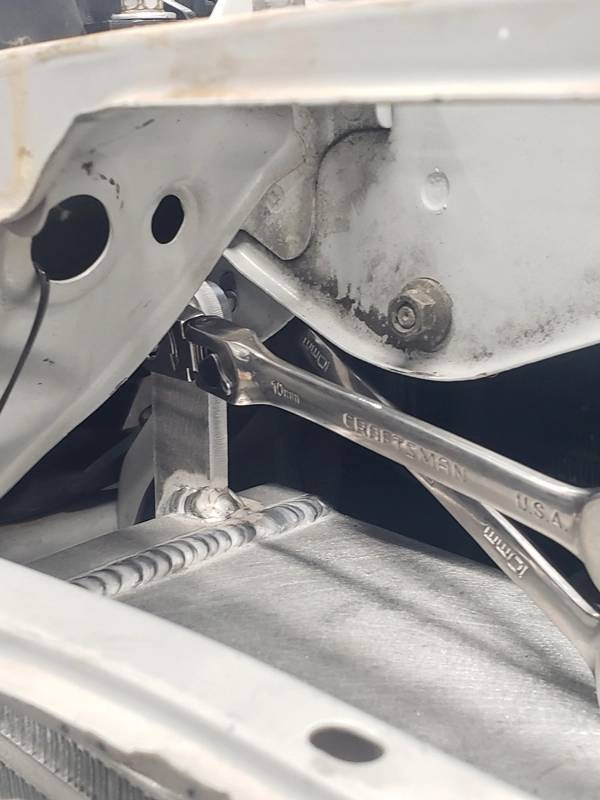
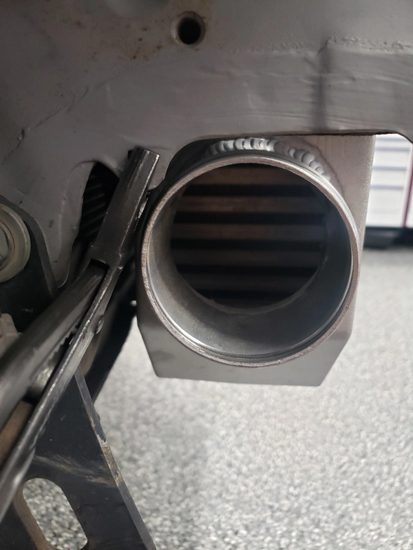
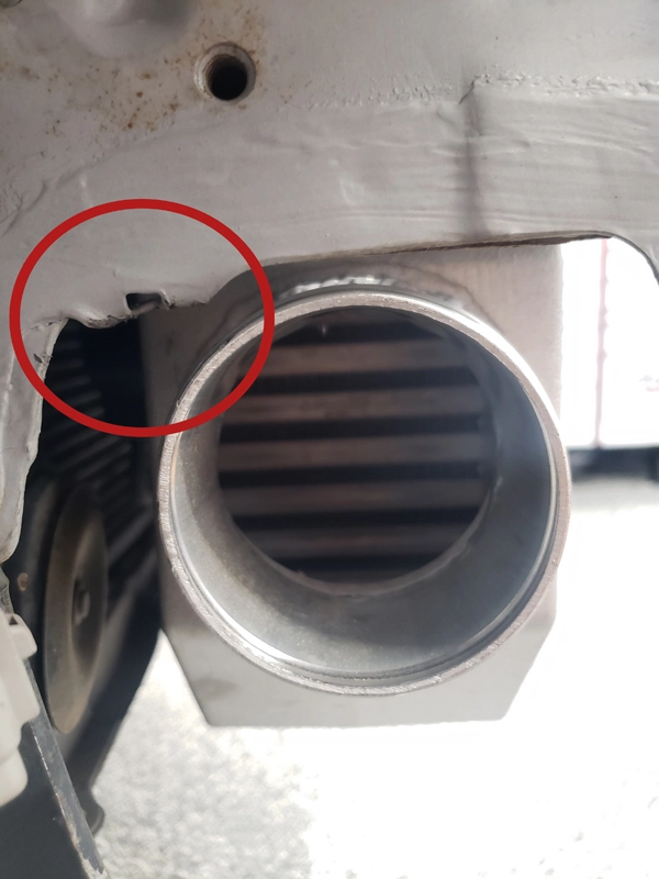
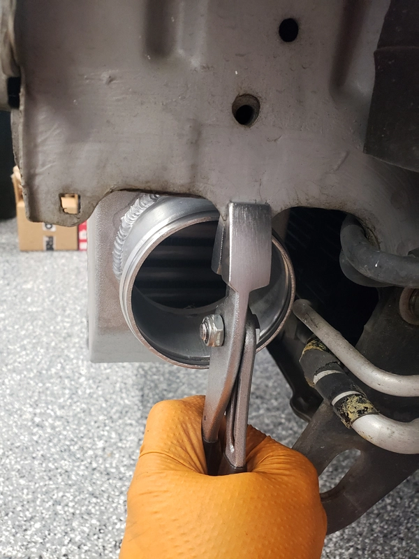
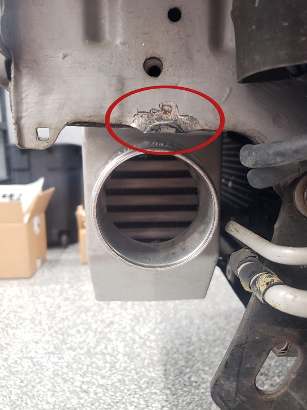
Step 10:
Using an appropriate tool, bend the tabs on frame rail near the intercooler inlet and outlet to gain clearance for charge pipe coupler. repeat on both sides.
Step 11:
Loosely install couplers onto both inlet and outlet of intercooler. The 2.5in to 3in adapter coupler goes on the intercooler inlet (sometimes called hot side or turbo discharge side).
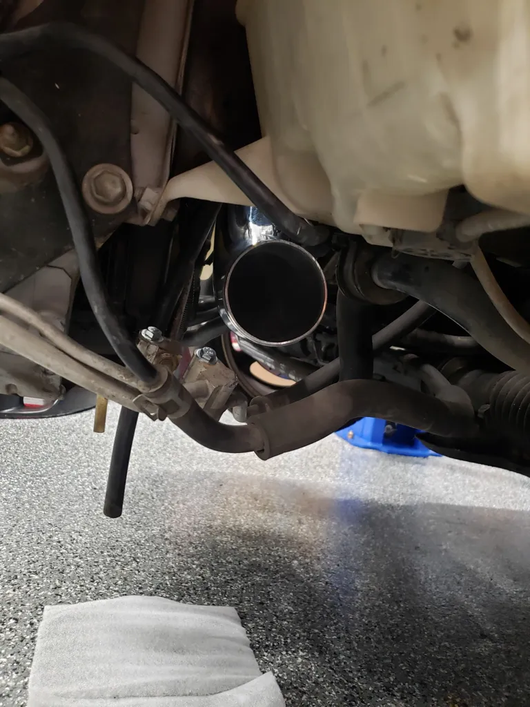
Step 12:
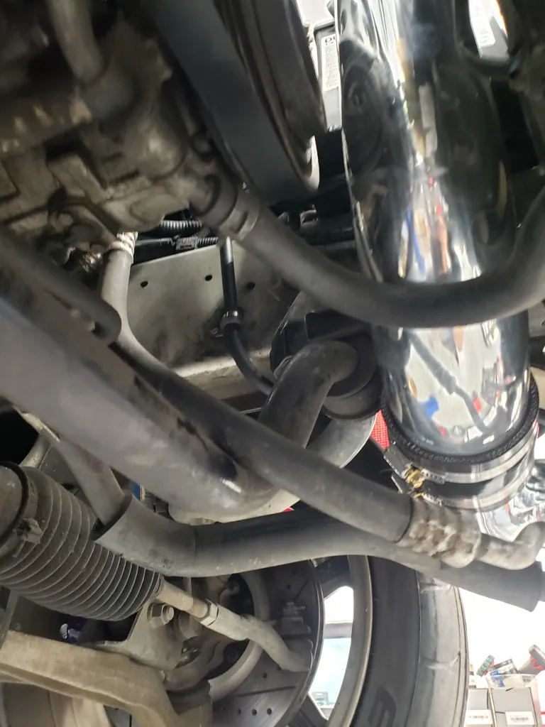
Loosely install turbo discharge pipe and route it under the sway bar. Make sure it is routed so that it will not come into contact with anything, such as: the alternator, power steering rack or lines, sway bar, or misc. wiring. Rotating the turbo compressor housing will most likely be required for proper charge pipe routing. 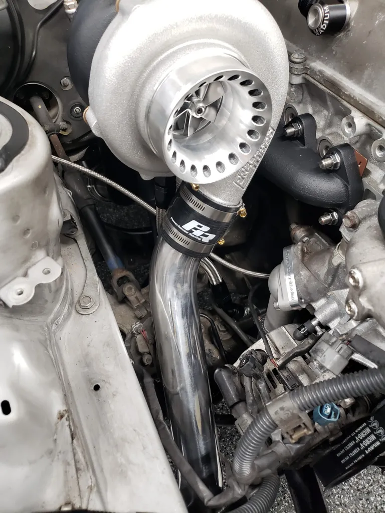
Step 13:
At first loosely install intercooler inlet charge pipe onto turbo discharge pipe and then into the intercooler inlet coupler. Once properly in position and with adequate clearance tighten all 6 supplied clamps as well as turbo compressor housing mounting bolts so it can no longer rotate. 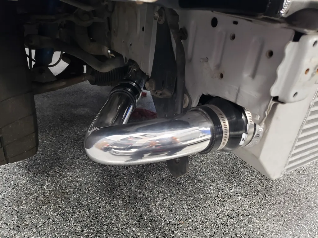
Step 14:
On left side remove a/c line to frame rail mounting bolts and lower the line down for easier access.
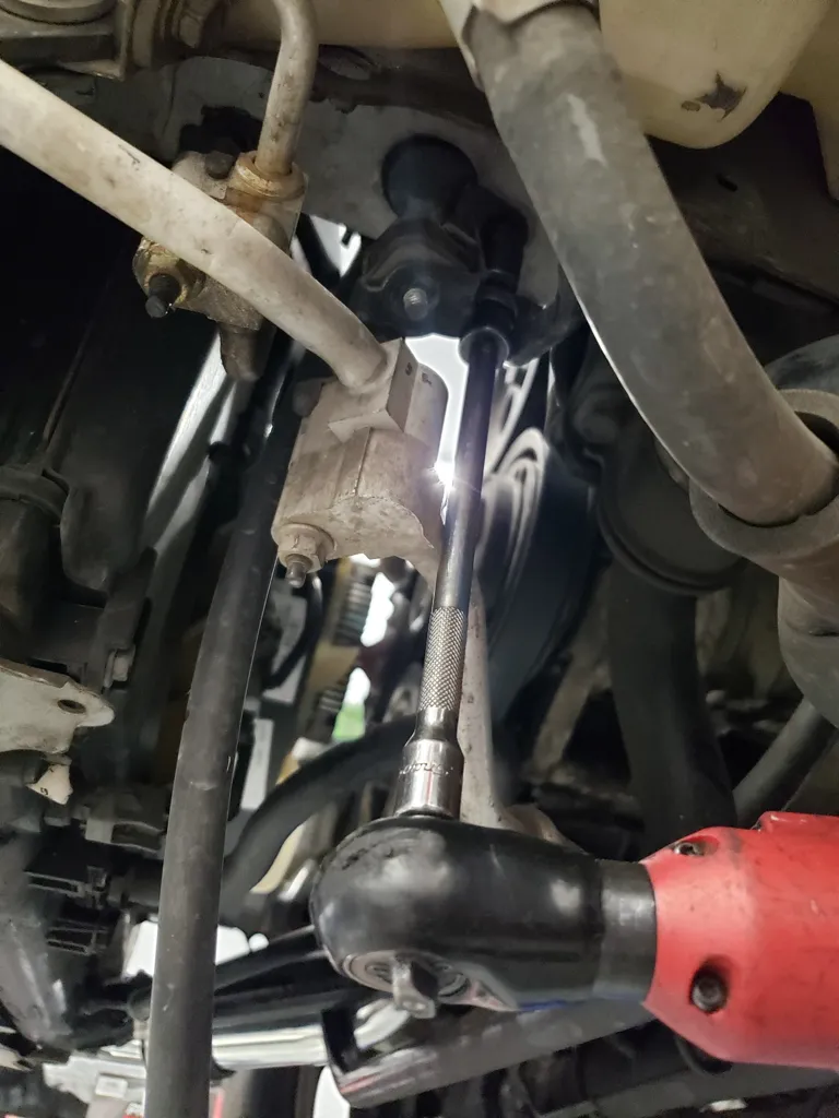
Step 15:
Using a large pair of vice grip pliers clamp down on the a/c line fittings so that you may remove there mounting brackets without releasing/discharging the a/c system.
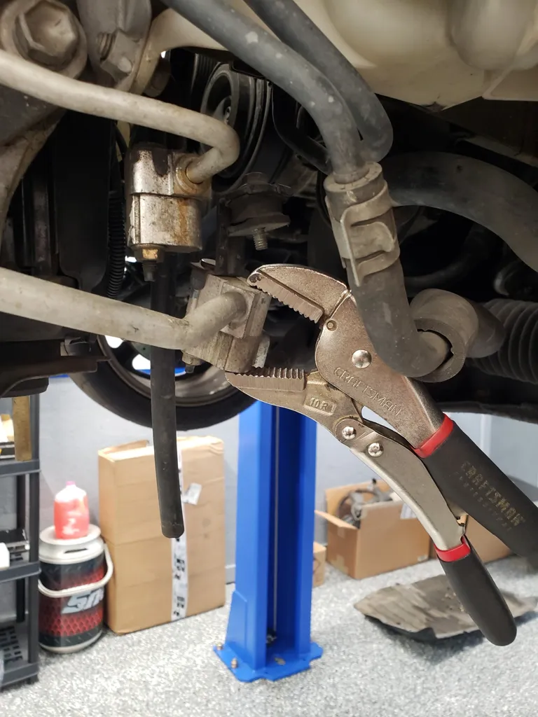
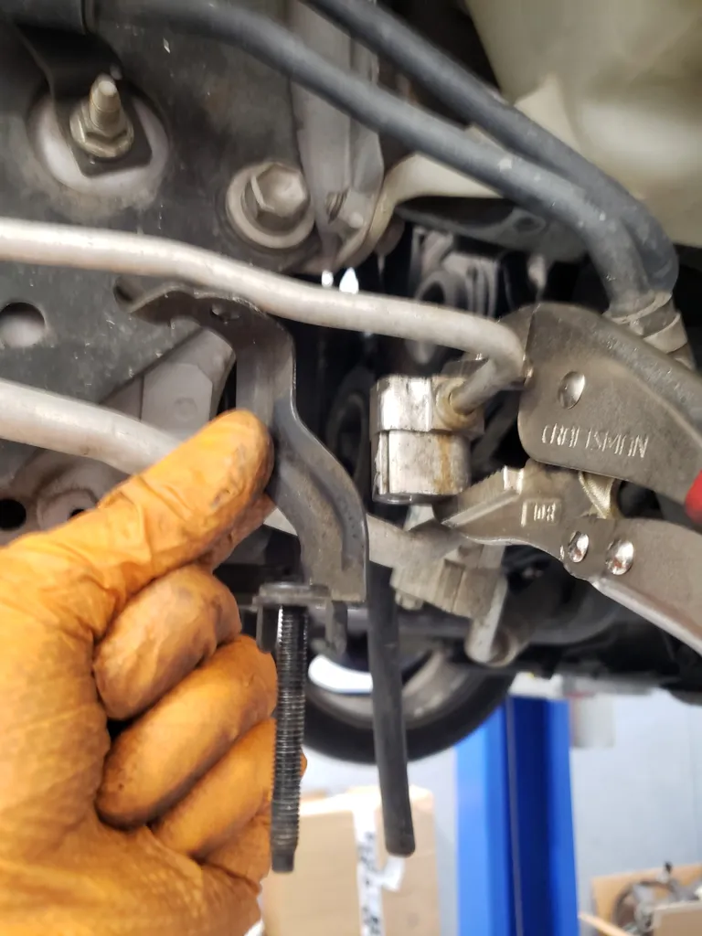
Step 16:
While clamped in the vice grips remove the factory m6 nut and mounting bracket. Then install the M6 bolt acquired in previous step along with factory M6 flange nut and tighten.
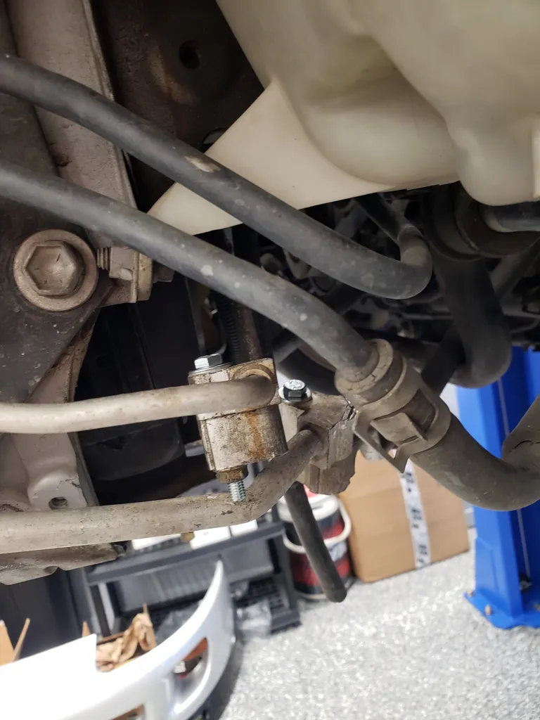
Step 17:
Remove vice grip pliers and repeat on the other a/c line. below is a view of M6 bolts installed and factory a/c line mounting brackets removed.
Step 18:
Gently bend a/c lines down to gain clearance for charge pipes.
Step 19:
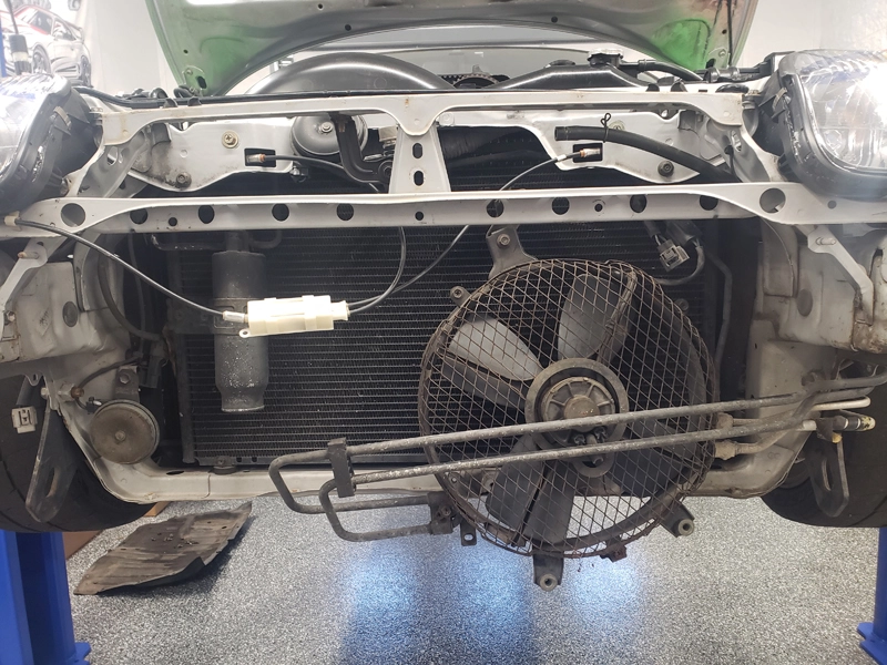
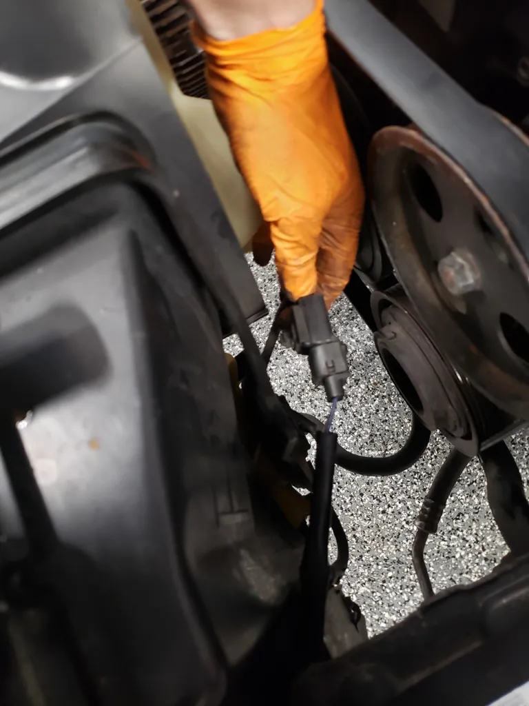
Depending on your model year of Supra as well as whether its auto or manual transmission you may have a radiator fan connector that needs to be repositioned for clearance. Remove it with its mounting clip from the radiator fan bracket
Step 20:
Remove the top mounting bolt of the radiator fan bracket and move fan bracket slightly to slip fan electrical connector onto opposite side of fan bracket and re clip in place using same clip hole in bracket. Reinstall top mounting bolt of fan bracket. If additional clearance is required in the following steps some grinding/material removal of the factory radiator fan bracket my be required. 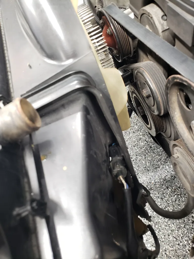
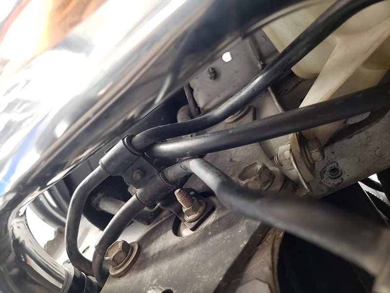
Step 21:
Gently route/bend the lower of the 2 power steering lines down for charge pipe clearance.
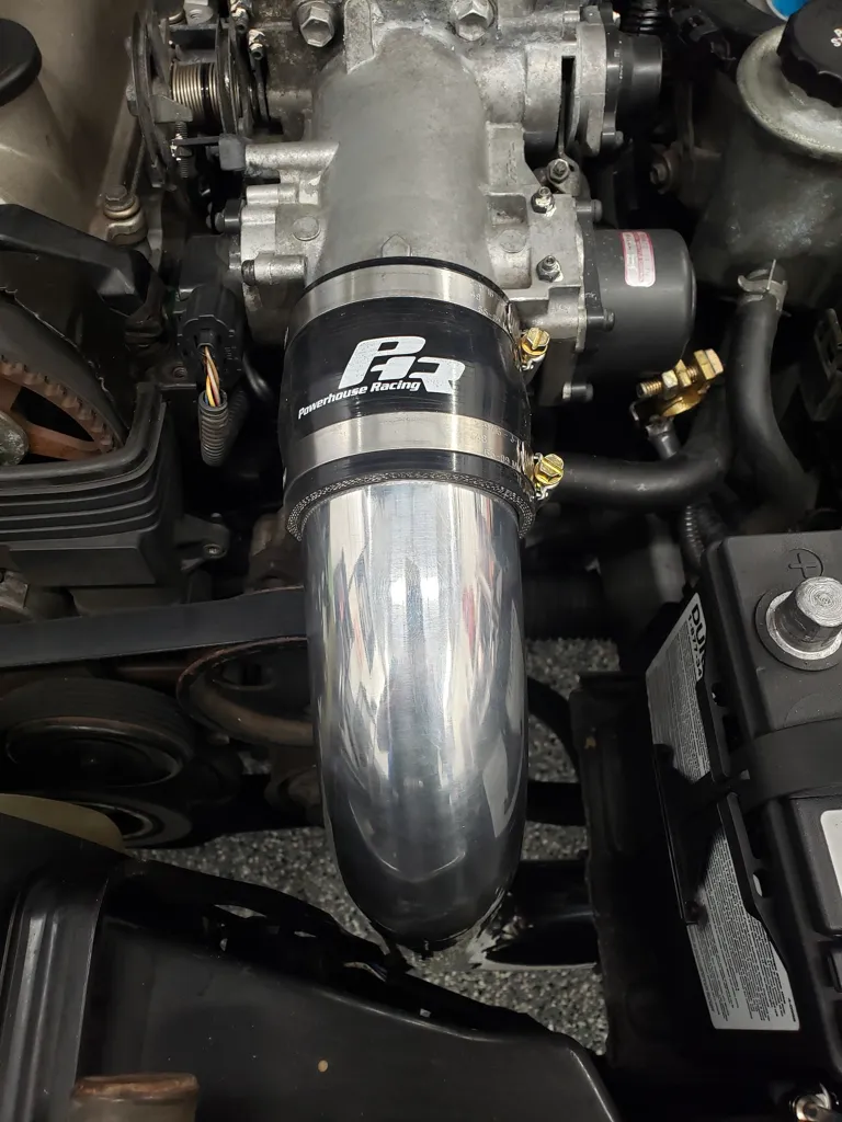
Step 22:
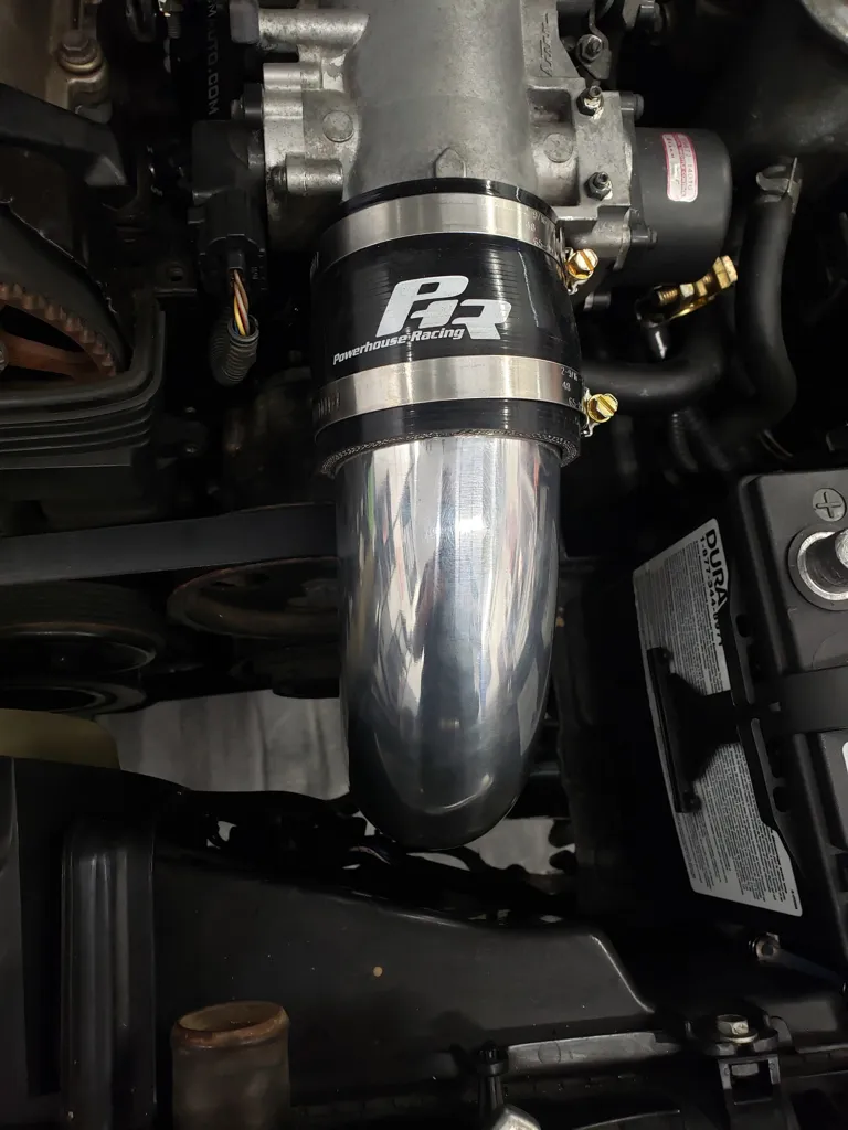
Loosely install throttle body inlet pipe and coupler onto throttle body. Check for clearance issues all around the pipe.
Step 23:
Install intercooler outlet pipe to throttle body inlet pipe then into coupler on intercooler outlet.
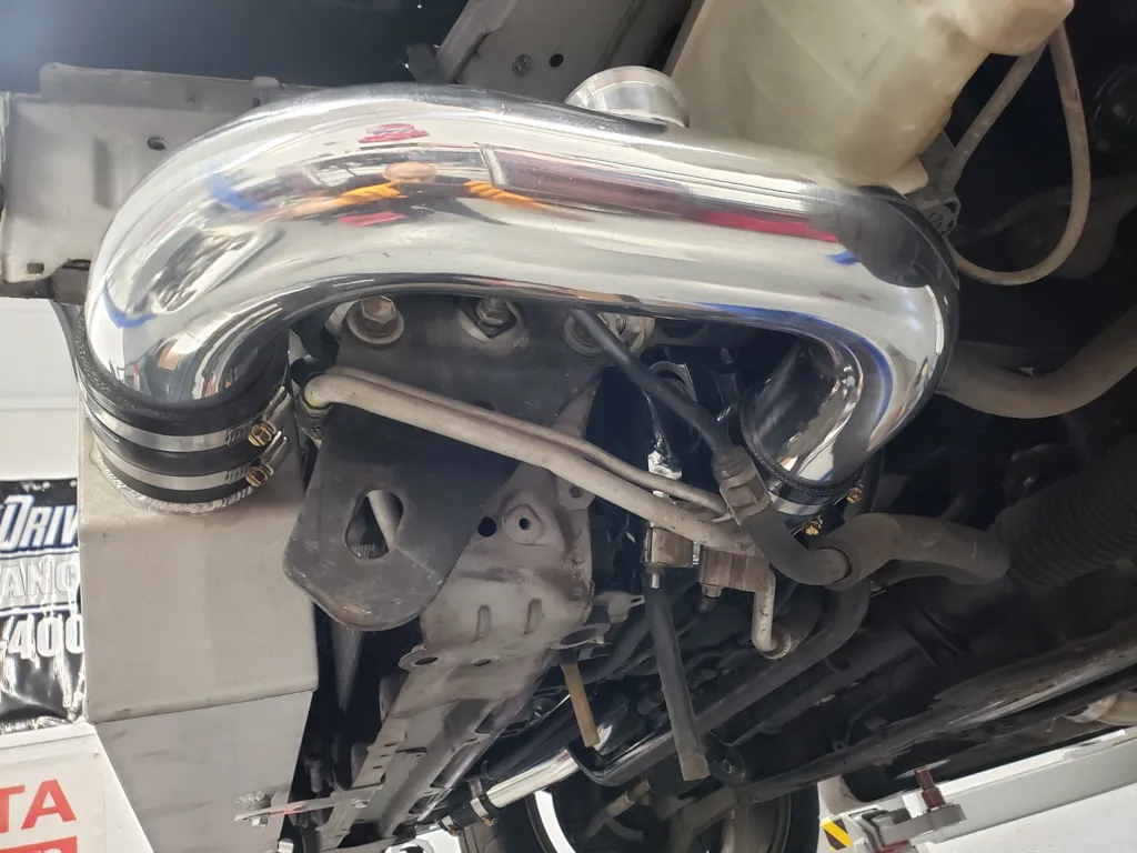
Step 24:
check and adjust for clearance between lines, charge pipes, and frame rail so that adequate clearance is had by all components and that no contact is made between any of them.
Step 25:
begin to tighten all 6 clamps starting at throttle body inlet coupler, while double checking for adequate clearance all around throttle body inly pipe. Adjust and recheck as necessary.
Step 26:
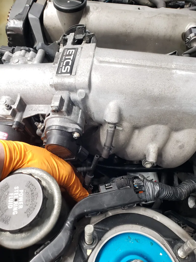
Preassemble BOV as needed per BOV manufacturer instructions based on engine idle vacuum. Some BOVs come with different springs while others have adjustment spring spacers. Most healthy 2JZGTE (non-vvti) engines produce about 20(+/-2) inches of vacuum at idle. Once properly assembled install BOV onto intercooler outlet pipe BOV flange. Make sure the O-ring seal is properly installed between the BOV and the flange.
Step 27:
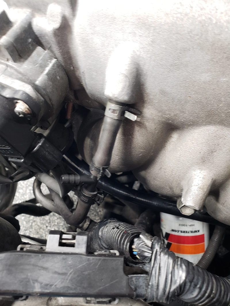
Cut and install a 1/4in vacuum tee into factory power steering idle up switch vacuum line. If power steering idle up switch has been disabled skip this step. (Use 10 x 10mm hose clamps on all 1/4in vacuum connections to ensure no leaks with develop(especially at high boost)
Step 28:
Measure and cut a 36in section of 1/4in vacuum hose if not supplied in kit and install onto tee from previous step
Step 29:
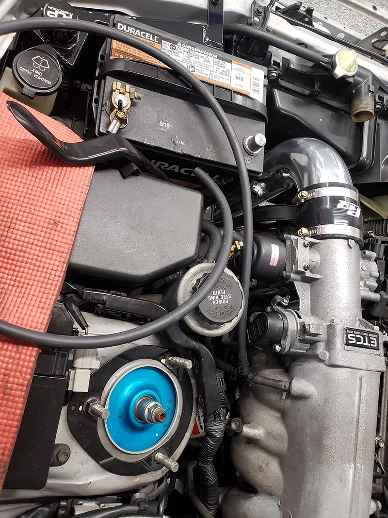
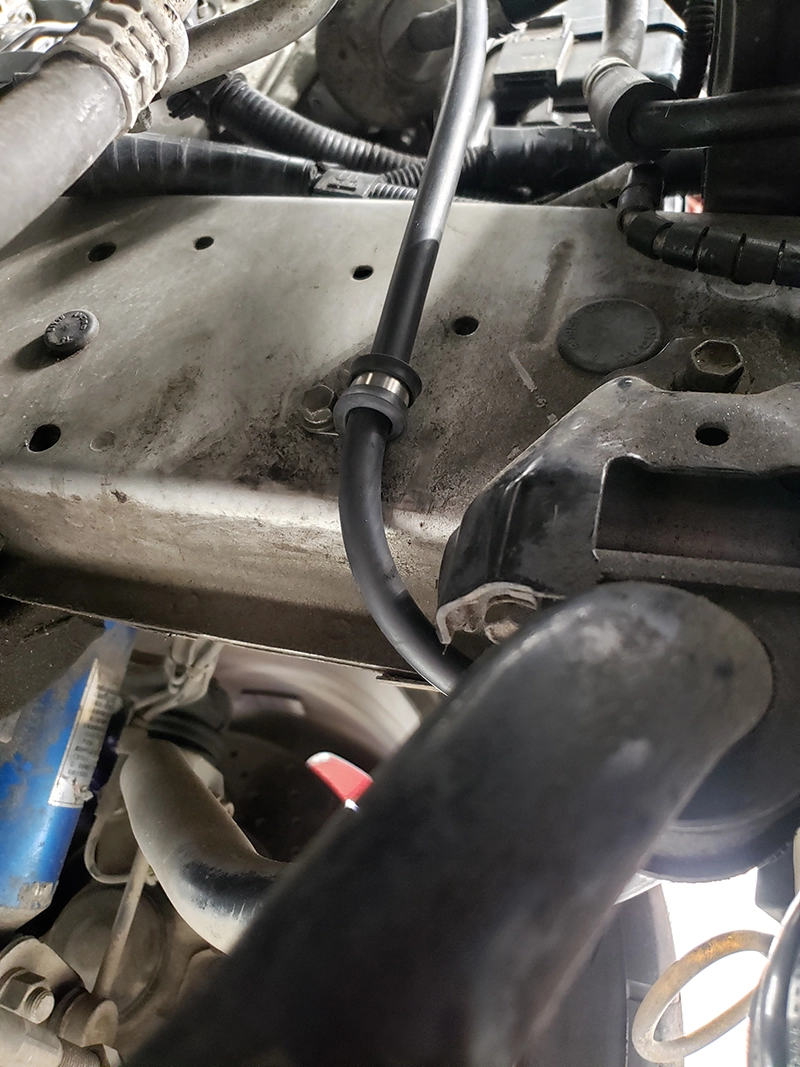
Route vacuum line down frame rail and over sway bar,
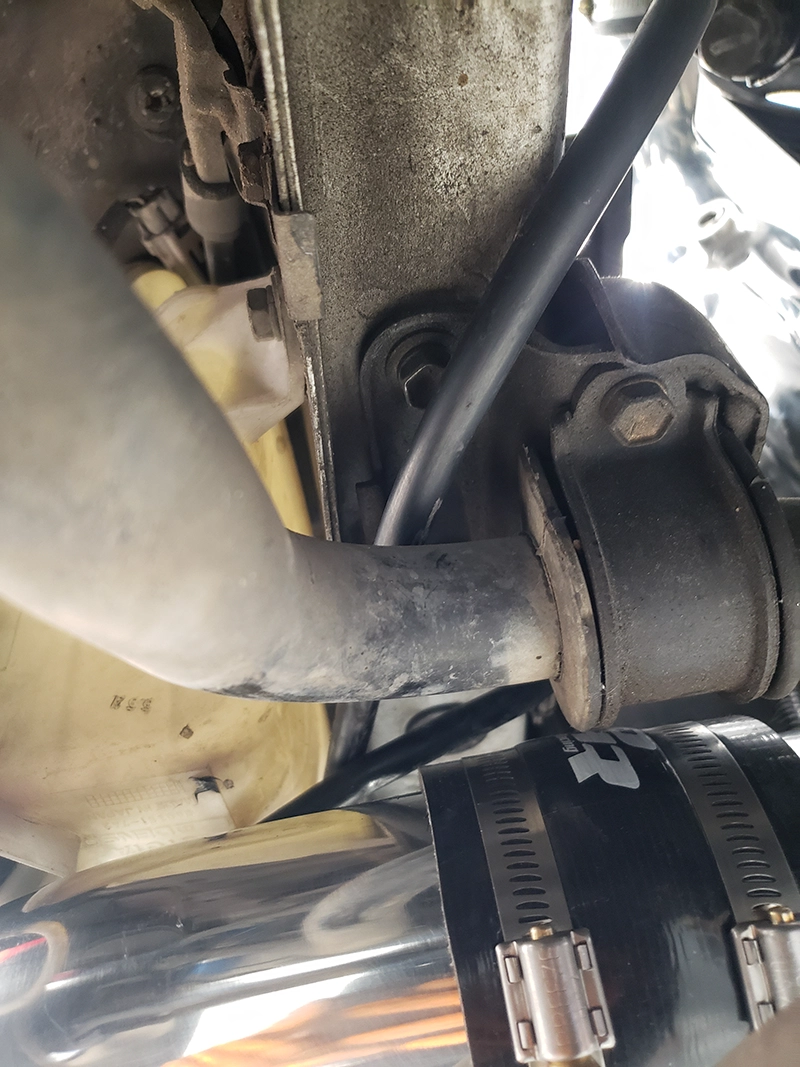
Step 30:
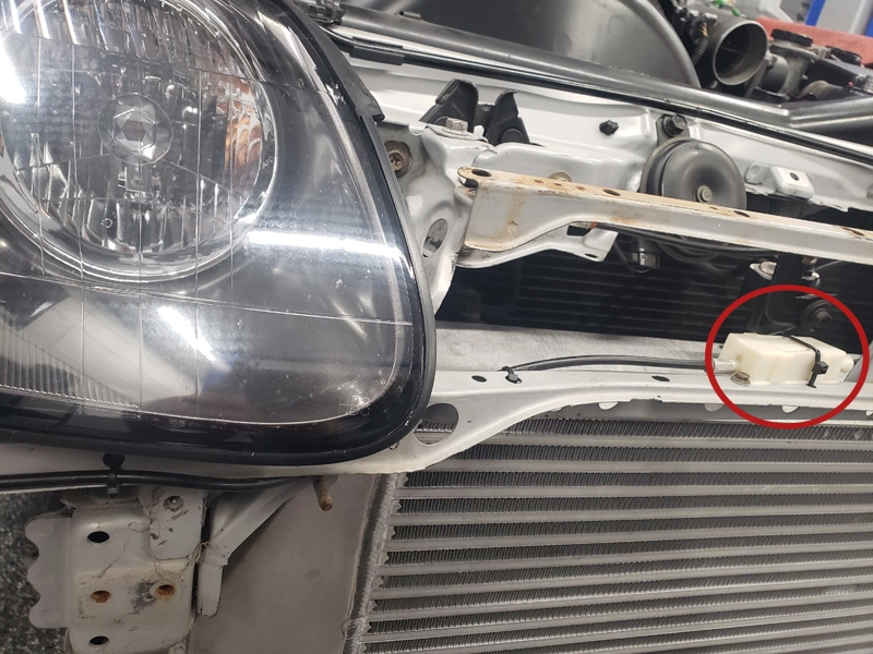
then route vacuum line down under the windshield washer reservoir and up towards BOV
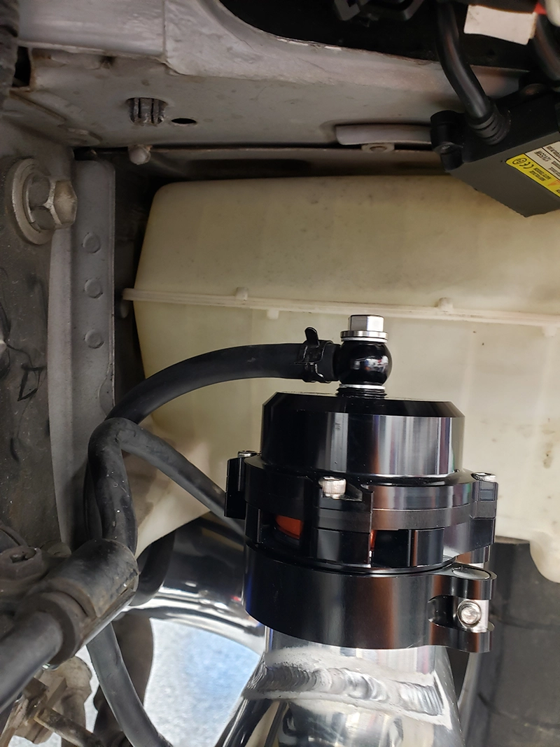
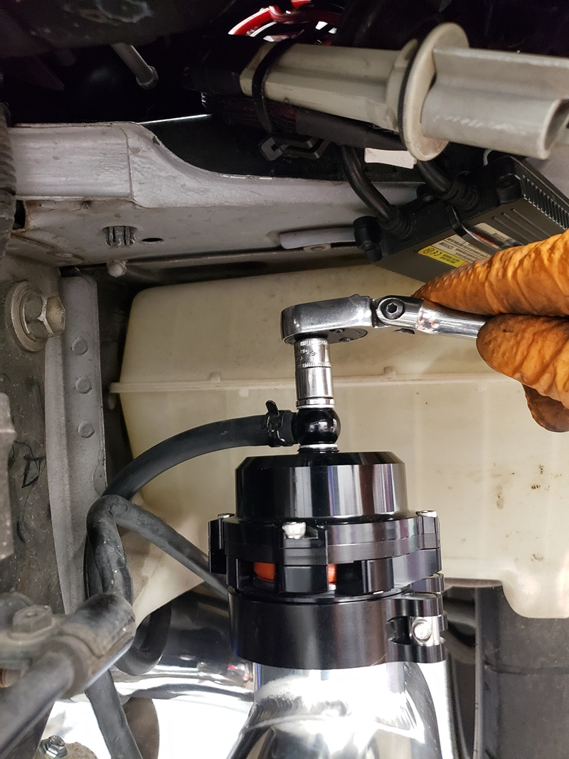
Step 31:
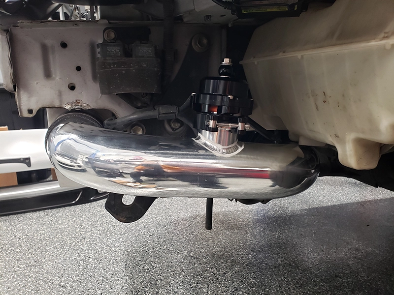
Install vacuum hose onto BOV vacuum port and rotate BOV vacuum port until adequate position is found, then tighten BOV vacuum port banjo fitting
Step 32:
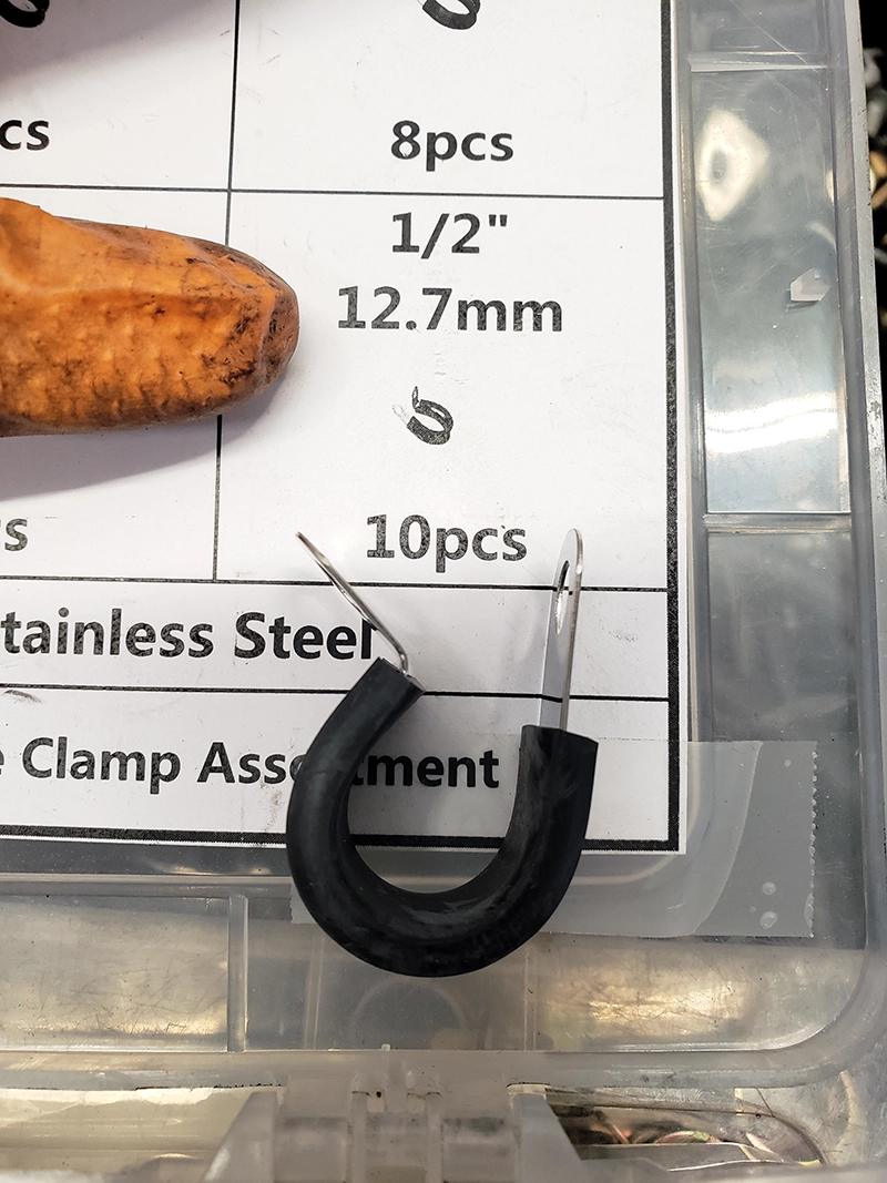
Install a 1/2in cushioned p-clamp (should be provided) around BOV vacuum hose and onto left side frame rail using an M6 bolt that was removed from the a/c line mounting brackets in previous step. An existing m6 threaded hole is used on left side frame rail.
Step 33:
Depending on what front bumper cover your Supra has some modification may be required for it to fit/reinstall properly. The following steps outline how to modify the bumper cover
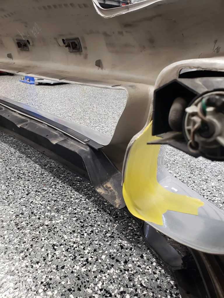
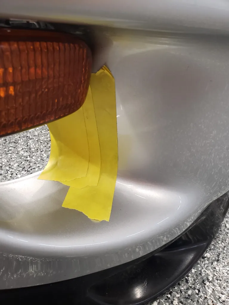
Step 34:
Test fit the bumper cover to see where the bumper cover contacts the intercooler pipes and needs to be modified. Then mark that area of the bumper cover.
(Tip: install painters tape on the painted side of bumper cover where ever modifications need to be made.)
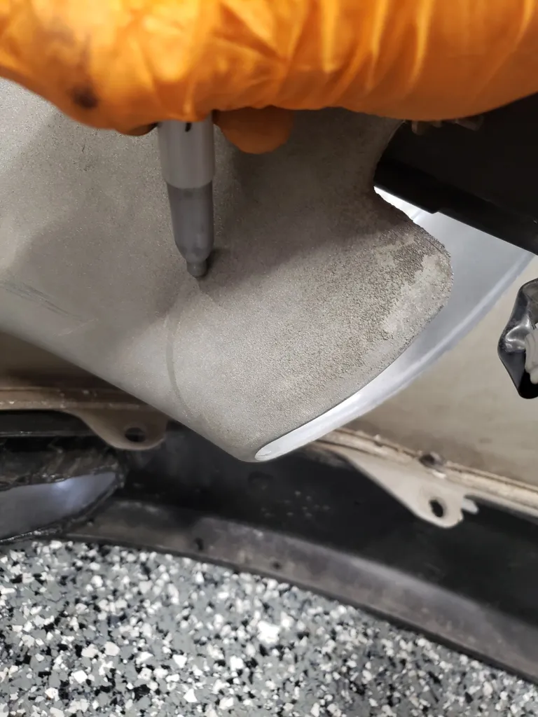
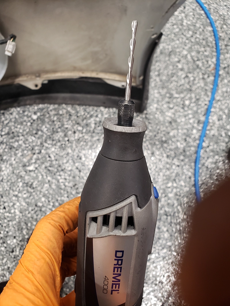
Step 35:
Use a Dremel and a router bit to make rough cuts where you previously marked the bumper cover for modification.
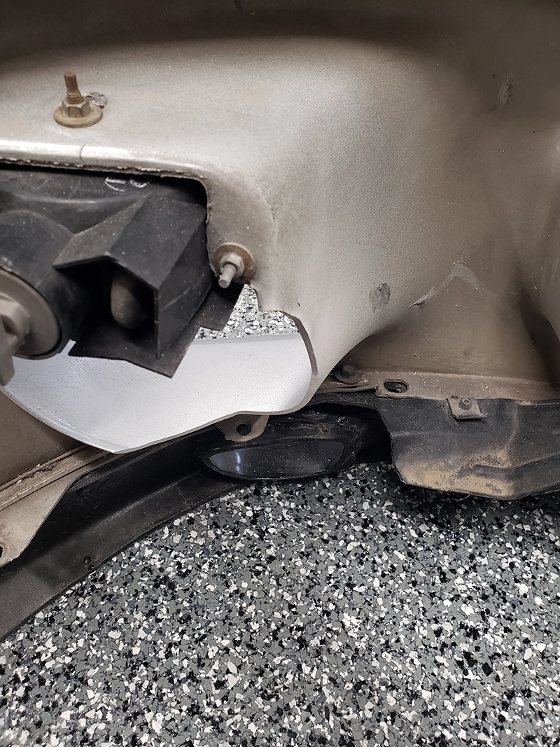
Step 36:
Once rough cuts have been made, test fit bumper cover and repeat that process as required till bumper cover fits properly. Once no more rough cuts need to be made and bumper cover fits properly use a small orbital sander and a 1inch sanding disc(fine grit) to smooth out the rough cuts and provide a natural and smooth contoured look back to the bumper cover. 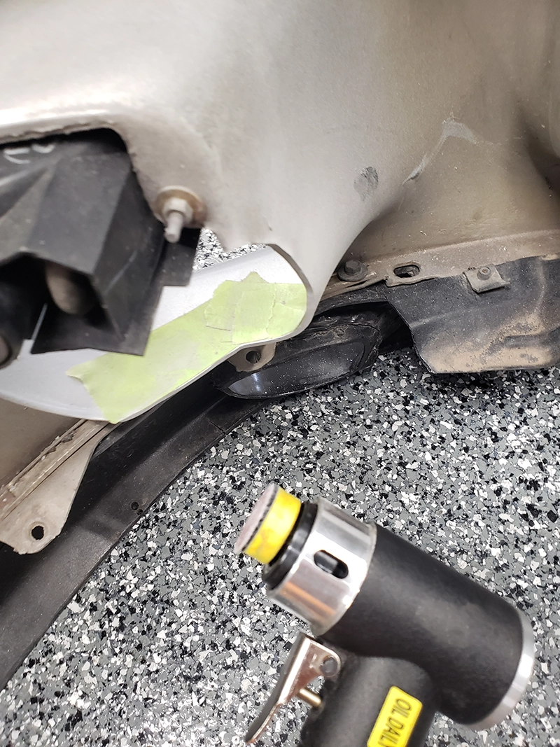
Step 37:
Remove the previously installed painters tape, and reinstall bumper cover for final time using all the factory mounting hardware and support brackets.
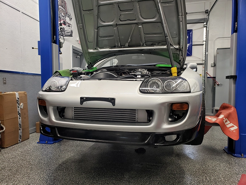
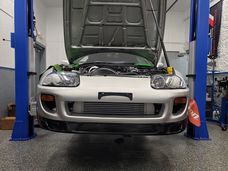
Your intercooler Kit is now installed and ready